26. ROS2-AI Vision Line Following Course
26.1 Line Locating
26.1.1 Program Logic
Before line following, program PuppyPi to locate the line first.
Firstly, program to recognize color. Use Lab color space to convert the image from RGB into Lab. Then, perform binaryzation, corrosion, dilation, etc., on the image to obtain the contour which contains the target color. Next, mark the contour with rectangle.
Next, acquire the diagonal points of the rectangle, and draw the center of line.
Lastly, display the information about the center of line on the terminal.
26.1.2 Operation Steps
Note
The input command should be case and space sensitive.
(1) Power on the robot, then follow the steps in 3.3 Docker Container Introduction and Entry and 3.4 ROS Version Switch Tool Guide to connect via the VNC remote control software and switch to the ROS 2 environment.
(2) Click  to open Terminator ROS2 terminal, then execute the following command in sequence:
ros2 launch example visual_patrol_demo.launch.py model:=0
(3) If want to close this game, we can press “Ctrl+C”. If it fails to close the game, please try again.
26.1.3 Program Outcome
Note
The program is default to recognize red.
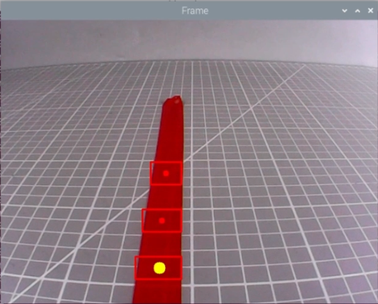
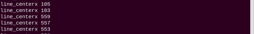
Use red electrical tape to set the line. Then place PuppyPi on the red line. After the line is recognized by PuppyPi, the line will be framed on the camera returned image and the center of line will be drawn. At the same time, the coordinate of the line center will be displayed on the terminal.
26.1.4 Program Analysis Analysis
The source code of this program is located within the Docker container at:
/home/ubuntu/ros2_ws/src/example/example/advanced_functions/visual_patrol_demo.py
Image Processing
(1) Import Function Package
4 5 6 7 8 9 10 11 12 13 14 15 | import cv2 import math import time import numpy as np import yaml from cv_bridge import CvBridge, CvBridgeError import rclpy from rclpy.node import Node from sensor_msgs.msg import Image from std_srvs.srv import Empty from puppy_control_msgs.msg import Velocity, Pose, Gait |
Import the required modules through import statements: math provides a range of mathematical functions and constants for related calculations; rospy is used for ROS communication; from sensor_msgs.msg import Image: import Image information type from sensor_msgs.msg. Sensor_msgs package provides information definition and camera image of various sensor data. Puppy control imports action group.
(2) Obtain the Maximal Contour
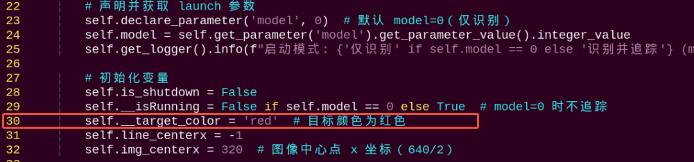
29 30 31 32 | self.__isRunning = False self.__target_color = 'red' self.line_centerx = -1 self.img_centerx = 320 |
Set the line color to red.
(3) Gussian Filtering
Before converting the image from RGB into Lab space, denoise the image and use GaussianBlur() function in cv2 library for Gaussian filtering.
frame_gb = cv2.GaussianBlur(frame_resize, (3, 3), 3)
The meaning of the parameters in bracket is as follow
The first parameter frame_resize is the input image
The second parameter (3, 3) is the size of Gaussian kernel
The third parameter 3 is the allowable variance around the average in Gaussian filtering. The larger the value, the larger the allowable variance.
(4) Binaryzation Processing
Adopt inRange() function in cv2 library to perform binaryzation on the image.
216 217 218 | frame_mask = cv2.inRange(frame_lab, np.array(color_range['min'], dtype=np.uint8), np.array(color_range['max'], dtype=np.uint8)) |
The line of code frame_mask = cv2.inRange(frame_lab, np.array(color_range['min'], dtype=np.uint8), np.array(color_range['max'], dtype=np.uint8)) uses the cv2.inRange function to create a binary mask.
(5) Open Operation and Close Operation
To reduce interference and make the image smoother, it is necessary to process the image.
220 221 | opened = cv2.morphologyEx(frame_mask, cv2.MORPH_OPEN, np.ones((5, 5), np.uint8)) closed = cv2.morphologyEx(opened, cv2.MORPH_CLOSE, np.ones((5, 5), np.uint8)) |
cv2.MORPH_OPEN refers to open operation where corrosion will be conducted first, then dilation. cv2.MORPH_CLOSE indicates close operation where dilation will be conducted first, then corrosion.
Take opened = cv2.morphologyEx(frame_mask, cv2.MORPH_OPEN, np.ones((6, 6), np.uint8)) for example. The meaning of the parameters in bracket is as follow.
① The first parameter frame_mask is the input image.
② The second parameter cv2.MORPH_OPEN refers to processing method, open operation.
③ The third parameter np.ones((6, 6), np.uint8) is frame size.
(6) Acquire the Maximum Contour
After processing the image, acquire the contour of the target to be recognized, which involves findContours() function in cv2 library.
231 232 233 | contours, _ = cv2.findContours(closed, cv2.RETR_EXTERNAL, cv2.CHAIN_APPROX_SIMPLE) cnt_large, area = self.getAreaMaxContour(contours) self.get_logger().debug(f"ROI {idx + 1}: 找到 {len(contours)} 个轮廓,最大面积为 {area}") |
The first parameter in the function’s parentheses is the input image; the second parameter is the contour retrieval mode; the third parameter is the contour approximation method.
The self.getAreaMaxContour function is called, passing the contours list, and it returns the largest contour cnt_large along with its corresponding area area.
178 179 180 181 182 183 184 185 186 187 188 189 190 | def getAreaMaxContour(self, contours): """找出面积最大的轮廓""" contour_area_max = 0 area_max_contour = None for c in contours: contour_area_temp = math.fabs(cv2.contourArea(c)) if contour_area_temp > contour_area_max: contour_area_max = contour_area_temp if contour_area_temp > 50: area_max_contour = c return area_max_contour, contour_area_max |
Acquire the Position
(1) Frame the Line
Call drawContours() function to set the rectangle pattern and frame the line.
cv2.drawContours(img, [box], -1, (0, 0, 255), 2)
(2) Draw the Center
Next, acquire the diagonal points of the rectangle, and draw the line center through circle() function.
245 246 247 248 249 | cv2.drawContours(img, [box], -1, (0, 0, 255), 2) pt1_x, pt1_y = box[0, 0], box[0, 1] pt3_x, pt3_y = box[2, 0], box[2, 1] center_x, center_y = (pt1_x + pt3_x) / 2, (pt1_y + pt3_y) / 2 cv2.circle(img, (int(center_x), int(center_y)), 5, (0, 0, 255), -1) |
26.1.5 Function Extension
Modify Default Recognition Color
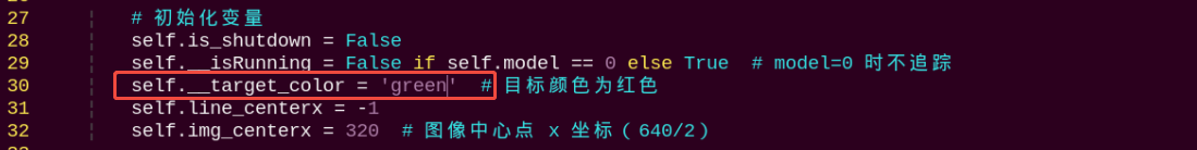
By default, the program is configured to recognize the color red as the target. The following steps demonstrate how to modify the default target color to green:
(1) Open a terminal  and run the following command to enter the directory containing the program:
cd ~/ros2_ws/src/example/example/advanced_functions
(2) Use the vim editor to open the program file:
vim visual_patrol_demo.py
(3) Find the line of code responsible for setting the target color. Refer to the image below for guidance.
Note
In vim, you can jump to a specific line by typing the line number, then pressing Shift + G.(Note: The line number shown in the image is for reference only. Please locate the actual line in your file.)
(4) Press the i key to enter insert mode, and change the line to: self.set_target('green')
(5) After editing, press the Esc key, then type the following to save and exit:
:wq
(6) Run the command below to restart the program and observe the updated behavior:
ros2 launch example visual_patrol_demo.launch.py model:=0
Adding a New Recognizable Color
In addition to the default colors configured in the program, users can add custom colors for recognition. This section provides step-by-step instructions for adding yellow as a new detectable color:
(1) Open a terminal and run the following command to enter the directory containing the program:
~/.stop_ros.sh
(2) Start the USB camera node with the following command:
ros2 launch peripherals usb_cam.launch.py
(3) Open a new terminal and navigate to the LAB Tool directory:
cd /home/ubuntu/software/lab_tool
(4) Run the PC software:
python3 main.py
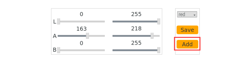
(5) Click the “Add” button located at the bottom right corner of the interface.

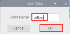
(6) In the popup dialog, enter “yellow” as the new color name and click “OK”.
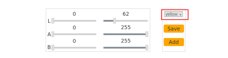
(7) From the color selection panel at the bottom right, select “yellow”.
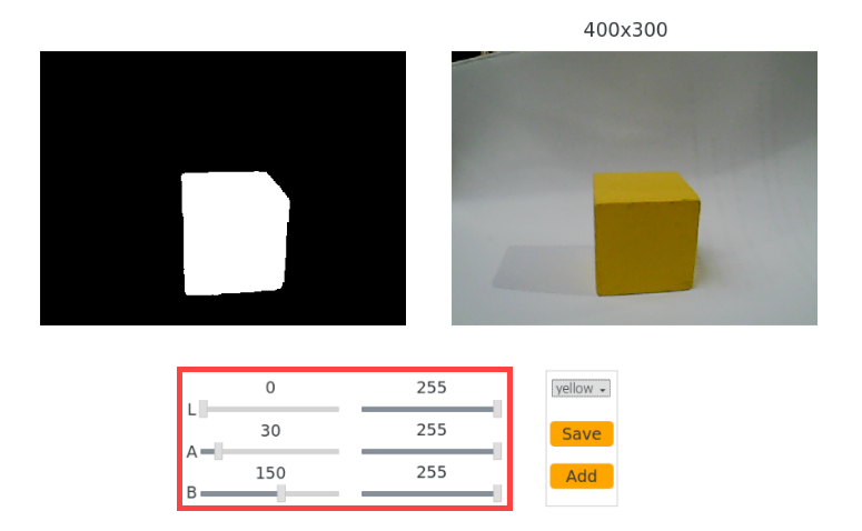
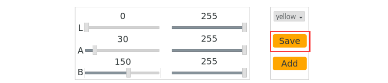
(8) Place a yellow object within the camera’s field of view. Adjust the L, A, and B sliders until the yellow area appears white on the left side of the interface, while all other areas appear black.
(9) After adjustment, click “Save” to save the settings, then close the LAB Tool.
(10) Verify that the new settings are saved correctly by opening the LAB configuration file:
cd software/lab_tool/ && vim lab_config.yaml
(11) Following the instructions in section “5.1 Modify Default Recognition Color”, modify the default detection color to yellow.
Note
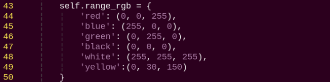
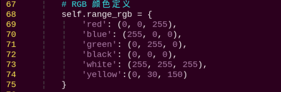
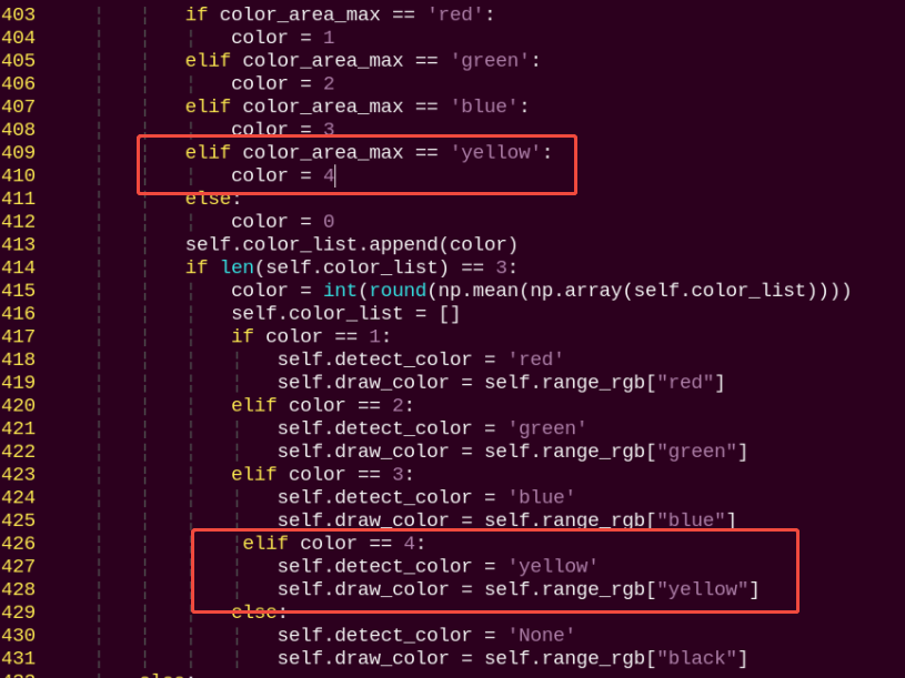
These three values represent the BGR color for the display font only and do not affect recognition accuracy. You can find appropriate BGR values online for customization. For yellow, use the BGR value (0, 30, 150). Add the corresponding LAB values for yellow to the color recognition code section as well.
(12) After completing the changes, restart the program with the following command. Place a yellow object in front of the camera to confirm it is correctly recognized in the output:
ros2 launch example visual_patrol_demo.launch.py model:=0
26.2 Auto Line Following
Note
If PuppyPi’s performance is not desired, we can debug according to “26.2.5 Function Extension -> Close Debugging Interface and Printed Data”.
26.2.1 Program Logic
PuppyPi can recognize the color of line and use algorithm to process the image so as to realize line following.
Firstly, program to recognize the color of line. Use Lab color space to convert the image from RGB into Lab. Then, perform binaryzation, corrosion, dilation, etc., on the image to obtain the contour which contains the target color. Next, mark the contour with rectangle.
After color recognition, perform calculation based on the location of line in the image to control PuppyPi to move along the line.
26.2.2 Operation Steps
Note
The input command should be case and space sensitive.
(1) Power on the robot, then follow the steps in 3.3 Docker Container Introduction and Entry and 3.4 ROS Version Switch Tool Guide to connect via the VNC remote control software and switch to the ROS 2 environment.
(2) Click  to open Terminator ROS2 terminal, then enter the following command:
ros2 launch example visual_patrol_demo.launch.py model:=1
(3) If want to close this game, we can press “Ctrl+C”. If it fails to close the game, please try again.
26.2.3 Program Outcome
Note
The program is default to detect red.
Use the red electrical tape to set the line, and place PuppyPi on the red line. After the game starts, it will move along the red line.

26.2.4 Program Analysis
The source code of this program is stored in the Docker container:
/home/ubuntu/ros2_ws/src/example/example/advanced_functions/visual_patrol_demo.py
Move Following the Line
In the first lesson, we introduced how to locate lines. Following that, we can use the line’s center coordinate information to control the robot to follow the line, as shown in the figure below.
193 194 195 196 197 198 199 200 201 202 203 204 205 206 207 208 209 210 211 212 213 214 215 216 217 218 219 220 221 222 223 224 225 | def run(self, img): """处理图像,检测红色线条并计算中心位置""" size = (320, 240) img_h, img_w = img.shape[:2] frame_resize = cv2.resize(img, size, interpolation=cv2.INTER_LINEAR) frame_gb = cv2.GaussianBlur(frame_resize, (3, 3), 3) centroid_x_sum = 0 weight_sum = 0 for idx, r in enumerate(self.roi): roi_h = self.roi_h_list[idx] blobs = frame_gb[r[0]:r[1], r[2]:r[3]] frame_lab = cv2.cvtColor(blobs, cv2.COLOR_BGR2LAB) detect_color = self.__target_color if detect_color in self.color_range_list: color_range = self.color_range_list[detect_color] frame_mask = cv2.inRange(frame_lab, np.array(color_range['min'], dtype=np.uint8), np.array(color_range['max'], dtype=np.uint8)) # 形态学操作 opened = cv2.morphologyEx(frame_mask, cv2.MORPH_OPEN, np.ones((5, 5), np.uint8)) closed = cv2.morphologyEx(opened, cv2.MORPH_CLOSE, np.ones((5, 5), np.uint8)) # 调试信息:显示掩模图像 cv2.imshow('Mask', closed) cv2.waitKey(1) else: self.line_centerx = -1 self.get_logger().warn(f"目标颜色 '{detect_color}' 不在颜色阈值列表中。") return img |
Walk
We mainly control the robot dog’s movement by calling the functions PuppyPosePub.publish(), PuppyGaitConfigPub.publish(), and PuppyVelocityPub.publish().
135 136 137 138 139 140 141 142 143 144 145 146 147 | # 发布初始姿态 pose_msg = Pose() pose_msg.stance_x = float(self.PuppyPose['stance_x']) pose_msg.stance_y = float(self.PuppyPose['stance_y']) pose_msg.x_shift = float(self.PuppyPose['x_shift']) pose_msg.height = float(self.PuppyPose['height']) pose_msg.roll = float(self.PuppyPose['roll']) pose_msg.pitch = float(self.PuppyPose['pitch']) pose_msg.yaw = float(self.PuppyPose['yaw']) pose_msg.run_time = int(500) self.PuppyPosePub.publish(pose_msg) self.get_logger().info("发布初始姿态。") time.sleep(0.2) |
The PuppyPosePub.publish() function is used to control the robot dog’s posture during movement.
For example, in the code PuppyPosePub.publish(stance_x=PuppyPose['stance_x'], stance_y=PuppyPose['stance_y'], x_shift=PuppyPose['x_shift'], height=PuppyPose['height'], pitch=PuppyPose['pitch'], roll=PuppyPose['roll']), the parameters inside the parentheses have the following meanings:
(1) The first parameter, stance_x, represents the additional distance between the robot dog’s four legs along the x-axis, measured in centimeters.
(2) The second parameter, stance_y, represents the additional distance between the four legs along the y-axis, measured in centimeters.
(3) The third parameter, x_shift, represents the distance the four legs move in the same direction along the x-axis. A smaller value results in the robot leaning forward while walking, and a larger value causes it to lean backward. Adjusting x_shift helps maintain the robot’s balance during movement, measured in centimeters.
(4) The fourth parameter, height, is the height of the robot dog, specifically the vertical distance from the tips of the feet to the thigh joint, measured in centimeters.
(5) The fifth parameter, roll, refers to the roll angle of the robot dog, measured in degrees.
(6) The sixth parameter, pitch, refers to the pitch angle of the robot dog, measured in degrees.
The Puppy.gait_config(overlap_time) function is used to control the robot dog’s gait during movement.
151 152 153 154 155 156 157 158 159 | # 发布步态配置 gait_msg = Gait() gait_msg.overlap_time = float(self.GaitConfig['overlap_time']) gait_msg.swing_time = float(self.GaitConfig['swing_time']) gait_msg.clearance_time = float(self.GaitConfig['clearance_time']) gait_msg.z_clearance = float(self.GaitConfig['z_clearance']) self.PuppyGaitConfigPub.publish(gait_msg) self.get_logger().info("发布步态配置。") time.sleep(0.2) |
For example, in the code Puppy.gait_config(overlap_time = GaitConfig['overlap_time'], swing_time = GaitConfig['swing_time'], clearance_time = GaitConfig['clearance_time'], z_clearance = GaitConfig['z_clearance']), the parameters inside the parentheses have the following meanings:
(1) The first parameter, overlap_time, represents the duration for which all four knee joints are in contact with the ground, measured in seconds.
(2) The second parameter, swing_time, represents the duration for which the knee joints are fully lifted off the ground, measured in seconds.
(3) The third parameter, clearance_time, refers to the time interval between the front and rear feet, measured in seconds.
(4) The fourth parameter, z_clearance, represents the height that the knee joints are lifted during movement, measured in centimeters.
26.2.5 Function Extension
Close Debugging Interface and Printed Data
As the continuous refresh of debugging interface and printed data on terminal will occupy CPU of Raspberry Pi, we can close debugging interface and printed data to tackle choppy running.
(1) Input the following command and press Enter to edit the program file.
cd ros2_ws/src/example/example/advanced_functions/
(2) Open the program file using the Vim editor by entering the following command:
vim visual_patrol_demo.py
(3) Next, jump to this line of code.


Note
we can input the line code and press “Shift+G” to jump to the corresponding line.
(4)Press “i” key to enter editing mode. Then add “#” in front of the codes in the red frame to comment.


(5) After modification, press “Esc” and input “:wq” and press Enter to save and exit editing.
:wq
(6) Input the following command to restart the game and check PuppyPi’s performance.
ros2 launch example visual_patrol_demo.launch.py model:=1
(7) If you need to view the debugging screen again (real-time feedback from the camera), you can uncomment the content boxed in step 3), i.e., remove the “#” in front of the code, then save, as shown in the following figure:


Change the Followed Color
The default target color for this feature is red. If you wish to change it—for example, to black—please refer to section 26.1.5 Function Extension for detailed instructions.
After making the necessary changes, enter the corresponding command to launch the feature.
ros2 launch example visual_patrol_demo.launch.py model:=1