8. ROS1-Depth Camera Applications
8.1 Depth Map Pseudo-Color Processing
8.1.1 Program Flow
First, initialize the node and obtain the RGB image and depth map topic messages.
Next, process the image to generate the pseudo-color image.
Finally, transmit both the color image and pseudo-color image.
8.1.2 Operation Steps
Note
The input command should be case sensitive, and the keywords can be complemented using Tab key.
(1) Double-click  to open the command line terminal, and execute the command below to terminate the auto-start service.
~/.stop_ros.sh
(2) Execute the following command and hit Enter to run the game.
roslaunch jetarm_6dof_rgbd_cam 1_get_depth_rgb_img.launch
(3) If you need to terminate the running program, use short-cut Ctrl+C.
(4) After completing the game experience, you must start the app service (if not started, it will affect the functionality of subsequent app features). In the terminal interface, enter the command and press Enter to launch the app service.
sudo systemctl start start_app_node.service
(5) After the service is initiated successfully, the robot will emit a beeping sound.
8.1.3 Program Outcome
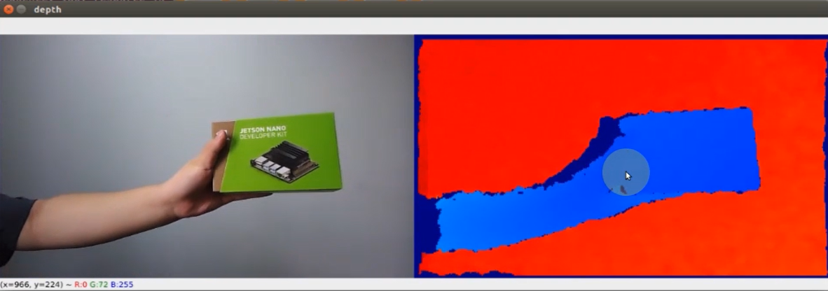
Once the game starts, the robot arm will send the RGB color image and depth image to the terminal. The color will change corresponding to the distance indicated in the depth map.
8.1.4 Launch File Analysis
The Launch file is saved in /home/ubuntu/jetarm/src/jetarm_example/src/jetarm_6dof_rgbd_cam /launch/1_get_depth_rgb_img.launch
Initiate base.launch file to invoke the robot arm basic settings.
2 | <include file="$(find jetarm_bringup)/launch/base.launch"/> |
Launch the source code file 1_get_depth_rgb_img.py using the node.
4 5 6 | <node name="get_depth_rgb" pkg="jetarm_6dof_rgbd_cam" type="1_get_depth_rgb_img.py" output="screen" respawn="true"> </node> </launch> |
8.1.5 Python Source Code Analysis
The source code is saved in /home/ubuntu/jetarm/src/jetarm_example/src/jetarm_6dof_rgbd_cam /scripts/1_get_depth_rgb_img.py
The program flowchart is as below:
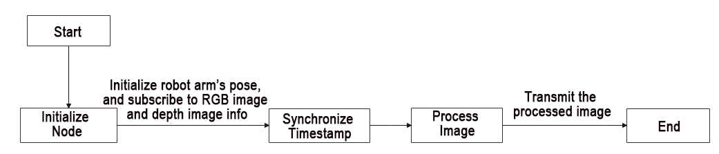
The program primarily involves capturing the RGB image and depth image from the camera. After processing the image, the program will then transmit it to the screen.
Import Feature Pack
To import the necessary modules through the import statement:
cv2 is used for OpenCV image processing.
rospy is utilized for ROS communication.
numpy is employed for array operations.
message_filters is incorporated for implementing message filtering and synchronization, handling sensor data and messages in ROS.
The Image message type is imported and renamed as RosImage.
The SetBool service message type is imported from the std_srvs.srv module.
The fps function module is imported from the vision_utils module for frame rate calculation.
queue is used for queue-related operations in multi-threading.
The ROS message type named MultiRawIdPosDur is imported from hiwonder_interfaces.msg for defining custom ROS messages to facilitate data transmission and communication within the ROS system.
The servo control module is imported from jetarm_sdk.
7 8 9 10 11 12 13 14 15 16 | import cv2 import rospy import numpy as np import message_filters from sensor_msgs.msg import Image as RosImage from std_srvs.srv import SetBool from vision_utils import fps import queue from hiwonder_interfaces.msg import MultiRawIdPosDur from jetarm_sdk import pid, bus_servo_control |
Initiate RgbDepthImageNode Class(RGB Depth Image Class)
Display pertinent prompts in the terminal. Initiate the RgbDepthImageNode class, and within the loop, call the node.image_proc() method until Ctrl+C is triggered or the ROS node is shut down. Provide log information indicating shutdown2.
68 69 70 71 72 73 74 75 76 77 78 79 80 81 82 83 84 85 | if __name__ == "__main__": print(''' ********************************************* * * * 此程序需要订阅深度摄像头节点,开启前请确保(The depth camera node needs to be subscribed for this program, please ensure that before starting) * * 已开启摄像头节点, 通过rostopic list可查看(The camera node has been started, please check via rostopic list) * * 是否有usb_cam相关节点,成功运行可看到终端(Whether there are usb_cam related nodes, you can see the terminal if it runs successfully) * * running ... * * * ********************************************* ''') try: node = RgbDepthImageNode() while not rospy.is_shutdown(): node.image_proc() except KeyboardInterrupt: rospy.loginfo("shutdown2") |
Initialization Function of RgbDepthImageNode Class
19 20 21 22 23 24 25 26 27 28 29 30 31 32 33 34 35 36 37 | class RgbDepthImageNode: def __init__(self): rospy.init_node('g1et_rgb_and_depth_image', anonymous=True) self.fps = fps.FPS() self.servos_pub = rospy.Publisher('/controllers/multi_id_pos_dur', MultiRawIdPosDur, queue_size=1) rospy.sleep(3) bus_servo_control.set_servos(self.servos_pub, 1000, ((1, 500), (2, 700), (3, 85), (4, 350), (5, 500), (10, 200))) rospy.sleep(2) rospy.wait_for_service('/rgbd_cam/set_ldp') rgb_sub = message_filters.Subscriber('/rgbd_cam/color/image_raw', RosImage, queue_size=1) depth_sub = message_filters.Subscriber('/rgbd_cam/depth/image_raw', RosImage, queue_size=1) rospy.ServiceProxy('/rgbd_cam/set_ldp', SetBool)(False) # 同步时间戳, 时间允许有误差在0.03s(synchronize timestamps, allowing for a time error of up to 0.03 seconds) sync = message_filters.ApproximateTimeSynchronizer([rgb_sub, depth_sub], 2, 0.02) sync.registerCallback(self.multi_callback) #执行反馈函数(execute feedback function) self.queue = queue.Queue(maxsize=1) |
Initialize the node g1et_rgb_and_depth_image.
19 20 21 | class RgbDepthImageNode: def __init__(self): rospy.init_node('g1et_rgb_and_depth_image', anonymous=True) |
Initialize the frame rate counter.
22 | self.fps = fps.FPS() |
Create Servo Publisher
The
servos_pubcreates a servo publisher, sending messages to the/controllers/multi_id_pos_durtopic. Here,MultiRawIdPosDuris the message type used to control the positions and durations of multiple servos.The
set_servosfunction from thebus_servo_controlmodule is utilized to set the initial position and duration of the servos. The parameters include the publisher instance, servo runtime (in milliseconds), and a tuple containing the IDs and rotation angles (ranging from 1-1000) of multiple servos.24 25 26 27
        self.servos_pub = rospy.Publisher('/controllers/multi_id_pos_dur', MultiRawIdPosDur, queue_size=1)
        rospy.sleep(3)
        bus_servo_control.set_servos(self.servos_pub, 1000, ((1, 500), (2, 700), (3, 85), (4, 350), (5, 500), (10, 200)))
        rospy.sleep(2)
Wait for the /rgbd_cam/set_ldp service to start. A service proxy is created, using the SetBool message type to specify the request and response types for the service. False is then passed to the /rgbd_cam/set_ldp service.
29 30 31 32 | rospy.wait_for_service('/rgbd_cam/set_ldp') rgb_sub = message_filters.Subscriber('/rgbd_cam/color/image_raw', RosImage, queue_size=1) depth_sub = message_filters.Subscriber('/rgbd_cam/depth/image_raw', RosImage, queue_size=1) rospy.ServiceProxy('/rgbd_cam/set_ldp', SetBool)(False) |
Synchronize Timestamp
Establish a time synchronizer to synchronize messages from the rgb_sub and depth_sub topics. The 2 signifies a maximum buffer size of 2 messages, and 0.03 implies that messages with a timestamp difference of no more than 0.03 seconds will be considered synchronized.
34 35 | # 同步时间戳, 时间允许有误差在0.03s(synchronize timestamps, allowing for a time error of up to 0.03 seconds) sync = message_filters.ApproximateTimeSynchronizer([rgb_sub, depth_sub], 2, 0.02) |
Call the multi_callback function.
36 | sync.registerCallback(self.multi_callback) #执行反馈函数(execute feedback function) |
A queue object, self.queue, has been created to store synchronized messages, with a maximum queue size set to 1.
37 | self.queue = queue.Queue(maxsize=1) |
multi_callback Function
The
multi_callbackfunction receives ROS image messages,ros_rgb_imageandros_depth_image.It checks whether
self.queueis empty. If the queue is empty, it places a tuple containing synchronizedros_rgb_imageandros_depth_imageinto the queue. This tuple represents two successfully synchronized image messages.39 40 41
def multi_callback(self, ros_rgb_image, ros_depth_image): if self.queue.empty(): self.queue.put_nowait((ros_rgb_image, ros_depth_image))
image_proc Function
43 44 45 46 47 48 49 50 51 52 53 54 55 56 57 58 59 60 61 62 63 64 65 | def image_proc(self): ros_rgb_image, ros_depth_image = self.queue.get(block=True) try: rgb_image = np.ndarray(shape=(ros_rgb_image.height, ros_rgb_image.width, 3), dtype=np.uint8, buffer=ros_rgb_image.data) rgb_image = rgb_image[40:440,] depth_image = np.ndarray(shape=(ros_depth_image.height, ros_depth_image.width), dtype=np.uint16, buffer=ros_depth_image.data) h, w = depth_image.shape[:2] depth = np.copy(depth_image).reshape((-1, )) depth[depth<=0] = 0 sim_depth_image = np.clip(depth_image, 0, 4000).astype(np.float64) sim_depth_image = sim_depth_image / 2000.0 * 255.0 bgr_image = cv2.cvtColor(rgb_image, cv2.COLOR_RGB2BGR) depth_color_map = cv2.applyColorMap(sim_depth_image.astype(np.uint8), cv2.COLORMAP_JET) result_image = np.concatenate([cv2.cvtColor(rgb_image, cv2.COLOR_RGB2BGR), depth_color_map], axis=1) cv2.imshow("depth", result_image) key = cv2.waitKey(1) if key != -1: rospy.signal_shutdown('shutdown1') except Exception as e: rospy.logerr('callback error:', str(e)) |
Retrieve synchronized RGB and depth image messages from the self.queue queue.
43 44 | def image_proc(self): ros_rgb_image, ros_depth_image = self.queue.get(block=True) |
Create a NumPy array, rgb_image, to store RGB image data. Extract data from ros_rgb_image and construct it based on image height, width, and data type. Crop the RGB image, retaining only the portion of rows from 40 to 440 pixels in height.
Create another NumPy array, depth_image, to store depth image data. Extract data from ros_depth_image and construct it based on image height and width. Obtain the height and width of the depth image.
45 46 47 48 49 50 | try: rgb_image = np.ndarray(shape=(ros_rgb_image.height, ros_rgb_image.width, 3), dtype=np.uint8, buffer=ros_rgb_image.data) rgb_image = rgb_image[40:440,] depth_image = np.ndarray(shape=(ros_depth_image.height, ros_depth_image.width), dtype=np.uint16, buffer=ros_depth_image.data) h, w = depth_image.shape[:2] |
Copy depth image data, rearranging it into a one-dimensional array. Set pixel values with depth values less than or equal to 0 to 0, eliminating invalid depth values.
Perform some processing on the depth image, truncating depth values between 0 and 4000, and converting the result to the np.float64 type.
Normalize and scale the depth image, mapping depth values to the range of 0 to 255 for display purposes.
52 53 54 55 | depth = np.copy(depth_image).reshape((-1, )) depth[depth<=0] = 0 sim_depth_image = np.clip(depth_image, 0, 4000).astype(np.float64) sim_depth_image = sim_depth_image / 2000.0 * 255.0 |
Convert the RGB image from the RGB color space to the BGR color space.
Utilize a Jet pseudocolor mapping to transform the depth image into a pseudocolored image.
Horizontally concatenate the RGB image and pseudocolored depth image into a single image.
Display the final image on the depth window using cv2.imshow.
56 57 58 59 | bgr_image = cv2.cvtColor(rgb_image, cv2.COLOR_RGB2BGR) depth_color_map = cv2.applyColorMap(sim_depth_image.astype(np.uint8), cv2.COLORMAP_JET) result_image = np.concatenate([cv2.cvtColor(rgb_image, cv2.COLOR_RGB2BGR), depth_color_map], axis=1) cv2.imshow("depth", result_image) |
Check for keyboard input, and if any key is pressed, close the node.
60 61 62 | key = cv2.waitKey(1) if key != -1: rospy.signal_shutdown('shutdown1') |
In the event of an exception in the code, capture the exception and record the error information as a ROS error log.
64 65 | except Exception as e: rospy.logerr('callback error:', str(e)) |
8.2 Distance Ranging
8.2.1 Program Flow
First, initialize the node and obtain the RGB image and depth map topic messages.
Next, process the image to obtain the pixel distance.
Finally, transmit both the color image and pseudo-color image.
8.2.2 Operation Steps
Note
the input command should be case sensitive, and the keywords can be complemented using Tab key.
(1) Double-click to open the command line terminal, and execute the following command to close the auto-start service.
~/.stop_ros.sh
(2) Run the following command and hit Enter to run the game program.
roslaunch jetarm_6dof_rgbd_cam 2_distance_measure.launch
(3) If you need to terminate the running program, use short-cut Ctrl+C.
(4) Following the above function, it is essential to enable the app service; otherwise, the app functions may be impacted. Execute the command below to initiate the app service.
sudo systemctl start start_app_node.service
(4) After the service is initiated successfully, the robot will emit a beeping sound.
8.2.3 Program Outcome
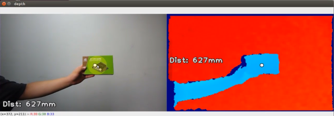
When the game begins, the robot arm will transmit both the RGB color image and depth image to the screen. The depth image will indicate the point closest to the screen along with its corresponding distance. You can generate a click point by left-clicking the mouse, and obtain the distance from this point. By double-clicking or pressing the mouse scroll, the marked point can be canceled, allowing the robot arm to resume measuring the minimal distance.
8.2.4 Launch File Analysis
The Launch file is saved in /home/ubuntu/jetarm/src/jetarm_example/src/jetarm_6dof_rgbd_cam /launch/2_distance_measure.launch
1 2 3 4 5 6 | <launch> <include file="$(find jetarm_bringup)/launch/base.launch"/> <node name="get_depth_rgb" pkg="jetarm_6dof_rgbd_cam" type="2_distance_measure.py" output="screen" respawn="true"> </node> </launch> |
Launch base.launch file and invoke the robot arm basic settings.
2 | <include file="$(find jetarm_bringup)/launch/base.launch"/> |
Launch 2_distance_measure.py source code file using the node.
4 5 | <node name="get_depth_rgb" pkg="jetarm_6dof_rgbd_cam" type="2_distance_measure.py" output="screen" respawn="true"> </node> |
8.2.5 Python Source Code Analysis
The source code file locates in /home/ubuntu/jetarm/src/jetarm_example/src/jetarm_6dof_rgbd_cam /scripts/2_distance_measure.py
The program flowchart is as below:
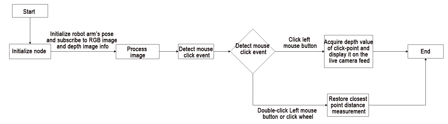
When the game begins, the robot arm will transmit both the RGB color image and depth image to the screen. The depth image will indicate the point closest to the screen along with its corresponding distance. You can generate a click point by left-clicking the mouse, and obtain the distance from this point. By double-clicking or pressing the mouse scroll, the marked point can be canceled, allowing the robot arm to resume measuring the minimal distance.
Import Feature Pack
To import the necessary modules through the import statement:
cv2 is used for OpenCV image processing.
rospy is utilized for ROS communication.
numpy is employed for array operations.
message_filters is incorporated for implementing message filtering and synchronization, handling sensor data and messages in ROS.
The Image message type is imported and renamed as RosImage.
The SetBool service message type is imported from the std_srvs.srv module.
The fps function module is imported from the vision_utils module for frame rate calculation.
queue is used for queue-related operations in multi-threading.
The ROS message type named MultiRawIdPosDur is imported from hiwonder_interfaces.msg for defining custom ROS messages to facilitate data transmission and communication within the ROS system.
The servo control module is imported from jetarm_sdk.
10 11 12 13 14 15 16 17 18 19 | import cv2 import rospy import numpy as np import message_filters from sensor_msgs.msg import Image as RosImage from std_srvs.srv import SetBool from vision_utils import fps import queue from hiwonder_interfaces.msg import MultiRawIdPosDur from jetarm_sdk import pid, bus_servo_control |
Initiate RgbDepthImageNode Class(RGB Depth Image Class)
Display pertinent prompts in the terminal. Initiate the RgbDepthImageNode class, and within the loop, call the node.image_proc() method until Ctrl+C is triggered or the ROS node is shut down. Provide log information indicating shutdown2.
105 106 107 108 109 110 111 112 113 114 115 116 117 118 119 120 121 122 | if __name__ == "__main__": print(''' ********************************************* * * * 此程序需要订阅深度摄像头节点,开启前请确保(The depth camera node needs to be subscribed for this program, please ensure that before starting) * * 已开启摄像头节点, 通过rostopic list可查看(The camera node has been started, please check via rostopic list) * * 是否有usb_cam相关节点,成功运行可看到终端(Whether there are usb_cam related nodes, you can see the terminal if it runs successfully) * * running ... * * * ********************************************* ''') try: node = RgbDepthImageNode() while not rospy.is_shutdown(): node.image_proc() except KeyboardInterrupt: rospy.loginfo("shutdown2") |
Initialization Function of RgbDepthImageNode Class
22 23 24 25 26 27 28 29 30 31 32 33 34 35 36 37 38 39 40 41 42 43 44 45 | class RgbDepthImageNode: def __init__(self): rospy.init_node('g1et_rgb_and_depth_image', anonymous=True) self.fps = fps.FPS() self.servos_pub = rospy.Publisher('/controllers/multi_id_pos_dur', MultiRawIdPosDur, queue_size=1) rospy.sleep(3) bus_servo_control.set_servos(self.servos_pub, 1000, ((1, 500), (2, 700), (3, 85), (4, 350), (5, 500), (10, 200))) rospy.sleep(2) rospy.wait_for_service('/rgbd_cam/set_ldp') rospy.ServiceProxy('/rgbd_cam/set_ldp', SetBool)(False) rgb_sub = message_filters.Subscriber('/rgbd_cam/color/image_raw', RosImage, queue_size=1) depth_sub = message_filters.Subscriber('/rgbd_cam/depth/image_raw', RosImage, queue_size=1) # 同步时间戳, 时间允许有误差在0.03s(synchronize timestamps, allowing for a time error of up to 0.03 seconds) sync = message_filters.ApproximateTimeSynchronizer([rgb_sub, depth_sub], 2, 0.03) sync.registerCallback(self.multi_callback) #执行反馈函数(execute feedback function) self.queue = queue.Queue(maxsize=1) self.target_point = None self.last_event = 0 cv2.namedWindow("depth") cv2.setMouseCallback('depth', self.click_callback) |
Initialize g1et_rgb_and_depth_image node
22 23 24 | class RgbDepthImageNode: def __init__(self): rospy.init_node('g1et_rgb_and_depth_image', anonymous=True) |
Initialize the frame rate counter.
25 | self.fps = fps.FPS() |
Create Servo Publisher
The servos_pub creates a servo publisher, sending messages to the /controllers/multi_id_pos_dur topic. Here, MultiRawIdPosDur is the message type used to control the positions and durations of multiple servos.
The set_servos function from the bus_servo_control module is utilized to set the initial position and duration of the servos. The parameters include the publisher instance, servo runtime (in milliseconds), and a tuple containing the IDs and rotation angles (ranging from 1-1000) of multiple servos.
27 28 29 30 | self.servos_pub = rospy.Publisher('/controllers/multi_id_pos_dur', MultiRawIdPosDur, queue_size=1) rospy.sleep(3) bus_servo_control.set_servos(self.servos_pub, 1000, ((1, 500), (2, 700), (3, 85), (4, 350), (5, 500), (10, 200))) rospy.sleep(2) |
Wait for /rgbd_cam/set_ldp Service to Start
A service proxy is created, using the SetBool message type to specify the request and response types for the service. False is then passed to the /rgbd_cam/set_ldp service.
32 33 | rospy.wait_for_service('/rgbd_cam/set_ldp') rospy.ServiceProxy('/rgbd_cam/set_ldp', SetBool)(False) |
Receive Image Information
(1) Create rgb_sub image information subscriber, and use message_filters.Subscriber to create a message subscriber.
The first parameter /rgbd_cam/color/image_raw represents the image topic name.
The second parameter RosImage is the message type.
The third parameter queue_size=1 specifies the size of the message queue.
(2) Create the depth_sub image information subscriber by utilizing message_filters.Subscriber. This subscriber is defined with the following specifications:
The first parameter /rgbd_cam/depth/image_raw represents the image topic name.
The second parameter indicates the message type as RosImage.
The third parameter queue_size=1 defines the message queue size.
35 36 | rgb_sub = message_filters.Subscriber('/rgbd_cam/color/image_raw', RosImage, queue_size=1) depth_sub = message_filters.Subscriber('/rgbd_cam/depth/image_raw', RosImage, queue_size=1) |
Synchronize Timestamp
Establish a time synchronizer to synchronize messages from the rgb_sub and depth_sub topics. The 2 signifies a maximum buffer size of 2 messages, and 0.03 implies that messages with a timestamp difference of no more than 0.03 seconds will be considered synchronized.
38 39 | # 同步时间戳, 时间允许有误差在0.03s(synchronize timestamps, allowing for a time error of up to 0.03 seconds) sync = message_filters.ApproximateTimeSynchronizer([rgb_sub, depth_sub], 2, 0.03) |
Invoke multi_callback function.
40 | sync.registerCallback(self.multi_callback) #执行反馈函数(execute feedback function) |
A queue object, self.queue, has been created to store synchronized messages, with a maximum queue size set to 1.
41 | self.queue = queue.Queue(maxsize=1) |
Initialize self.target_point and self.last_event.
41 42 43 | self.queue = queue.Queue(maxsize=1) self.target_point = None self.last_event = 0 |
cv2.namedWindow is used to create an OpenCV window named depth.
cv2.setMouseCallback invokes self.click_callback callback function to process the mouse event on the depth window.
44 45 | cv2.namedWindow("depth") cv2.setMouseCallback('depth', self.click_callback) |
click_callback Function
47 48 49 50 51 52 53 54 55 | def click_callback(self, event, x, y, flags, params): if event == cv2.EVENT_RBUTTONDOWN or event == cv2.EVENT_MBUTTONDOWN or event == cv2.EVENT_LBUTTONDBLCLK: self.target_point = None if event == cv2.EVENT_LBUTTONDOWN and self.last_event != cv2.EVENT_LBUTTONDBLCLK: if x >= 640: self.target_point = (x - 640, y) else: self.target_point = (x, y) self.last_event = event |
Firstly, check the type of mouse event, utilizing the mouse event constants from OpenCV. If the event is one of EVENT_RBUTTONDOWN (right button click), EVENT_MBUTTONDOWN (middle button click), or EVENT_LBUTTONDBLCLK (left button double click), set self.target_point to None.
47 48 49 | def click_callback(self, event, x, y, flags, params): if event == cv2.EVENT_RBUTTONDOWN or event == cv2.EVENT_MBUTTONDOWN or event == cv2.EVENT_LBUTTONDBLCLK: self.target_point = None |
If the detected mouse event is EVENT_LBUTTONDOWN (left button click) and the previous mouse event was not EVENT_LBUTTONDBLCLK (left button double click), check the mouse click position x and y. If x is greater than or equal to 640, set self.target_point to (x - 640, y); otherwise, set self.target_point to (x, y), recording the coordinates of the target point.
Finally, update the self.last_event variable to store the type of the current event.
50 51 52 53 54 55 | if event == cv2.EVENT_LBUTTONDOWN and self.last_event != cv2.EVENT_LBUTTONDBLCLK: if x >= 640: self.target_point = (x - 640, y) else: self.target_point = (x, y) self.last_event = event |
image_proc Function
62 63 64 65 66 67 68 69 70 71 72 73 74 75 76 77 78 79 80 81 82 83 84 85 86 87 88 89 90 91 92 93 94 95 96 97 98 99 100 101 102 | def image_proc(self): ros_rgb_image, ros_depth_image = self.queue.get(block=True) try: rgb_image = np.ndarray(shape=(ros_rgb_image.height, ros_rgb_image.width, 3), dtype=np.uint8, buffer=ros_rgb_image.data) depth_image = np.ndarray(shape=(ros_depth_image.height, ros_depth_image.width), dtype=np.uint16, buffer=ros_depth_image.data) h, w = depth_image.shape[:2] depth = np.copy(depth_image).reshape((-1, )) depth[depth<=0] = 55555 min_index = np.argmin(depth) min_y = min_index // w min_x = min_index - min_y * w if self.target_point is not None: min_x, min_y = self.target_point sim_depth_image = np.clip(depth_image, 0, 2000).astype(np.float64) / 2000 * 255 depth_color_map = cv2.applyColorMap(sim_depth_image.astype(np.uint8), cv2.COLORMAP_JET) txt = 'Dist: {}mm'.format(depth_image[min_y, min_x]) cv2.circle(depth_color_map, (int(min_x), int(min_y)), 8, (32, 32, 32), -1) cv2.circle(depth_color_map, (int(min_x), int(min_y)), 6, (255, 255, 255), -1) cv2.putText(depth_color_map, txt, (11, 200), cv2.FONT_HERSHEY_PLAIN, 2.0, (32, 32, 32), 6, cv2.LINE_AA) cv2.putText(depth_color_map, txt, (10, 200), cv2.FONT_HERSHEY_PLAIN, 2.0, (240, 240, 240), 2, cv2.LINE_AA) bgr_image = cv2.cvtColor(rgb_image[40:440, ], cv2.COLOR_RGB2BGR) cv2.circle(bgr_image, (int(min_x), int(min_y)), 8, (32, 32, 32), -1) cv2.circle(bgr_image, (int(min_x), int(min_y)), 6, (255, 255, 255), -1) cv2.putText(bgr_image, txt, (11, h - 20), cv2.FONT_HERSHEY_PLAIN, 2.0, (32, 32, 32), 6, cv2.LINE_AA) cv2.putText(bgr_image, txt, (10, h - 20), cv2.FONT_HERSHEY_PLAIN, 2.0, (240, 240, 240), 2, cv2.LINE_AA) self.fps.update() bgr_image = self.fps.show_fps(bgr_image) result_image = np.concatenate([bgr_image, depth_color_map], axis=1) cv2.imshow("depth", result_image) key = cv2.waitKey(1) if key != -1: rospy.signal_shutdown('shutdown1') except Exception as e: rospy.logerr('callback error:', str(e)) |
Retrieve synchronized RGB and depth image messages from the self.queue.
62 63 | def image_proc(self): ros_rgb_image, ros_depth_image = self.queue.get(block=True) |
Create a NumPy array, rgb_image, to store RGB image data. Extract data from ros_rgb_image and construct it based on the image’s height, width, and data type.
Create another NumPy array, depth_image, to store depth image data. Extract data from ros_depth_image and construct it based on the image’s height and width.
Retrieve the height and width of the depth image.
64 65 66 67 68 | try: rgb_image = np.ndarray(shape=(ros_rgb_image.height, ros_rgb_image.width, 3), dtype=np.uint8, buffer=ros_rgb_image.data) depth_image = np.ndarray(shape=(ros_depth_image.height, ros_depth_image.width), dtype=np.uint16, buffer=ros_depth_image.data) h, w = depth_image.shape[:2] |
Acquire Minimal Depth Pixel Point Coordinate
Copy the depth image data and reassemble it into a one-dimensional array.
Set pixel values with depth less than or equal to 0 to 55555, eliminating invalid depth values.
Find the index of the pixel with the minimum depth value in the depth image using np.argmin(depth).
70 71 72 | depth = np.copy(depth_image).reshape((-1, )) depth[depth<=0] = 55555 min_index = np.argmin(depth) |
Calculate the row coordinate min_y of the pixel with the minimum depth value by performing integer division using min_index divided by w (image width). Integer division truncates the decimal part, resulting in an integer representing the row position of the pixel with the minimum depth value in the depth image.
Multiply min_y by w (image width) and subtract the result from min_index to obtain the column coordinate min_x of the pixel with the minimum depth value.
73 74 | min_y = min_index // w min_x = min_index - min_y * w |
If target_point is not empty, assign its values to min_x and min_y, respectively.
75 76 | if self.target_point is not None: min_x, min_y = self.target_point |
Limit the depth values in the depth image to the range of 0 to 2000, then scale them to the range of 0 to 255 for visualizing depth information as a pseudocolored image.
Convert the depth image to a pseudocolored image using the Jet pseudocolor mapping.
78 79 | sim_depth_image = np.clip(depth_image, 0, 2000).astype(np.float64) / 2000 * 255 depth_color_map = cv2.applyColorMap(sim_depth_image.astype(np.uint8), cv2.COLORMAP_JET) |
Mark Corresponding Depth Values On Deep Pseudo-Color Image
Utilizing the depth values from the depth image (depth_image) at the corresponding coordinates (min_y, min_x), draw filled black and white circles on the deep pseudo-color image. These circles serve to highlight the position of the minimum depth value. The parameters include the image name, circle center coordinates, circle radius, circle colors (with -1 indicating filling the entire circle). The white circle is slightly smaller than the black circle for better emphasis.
Additionally, display text on the deep pseudo-color image representing the depth values. This involves drawing a larger black text and a slightly offset smaller gray text on the image. The parameters include the image being processed, text content, starting position, font, size, color, line width, and an option to enable anti-aliasing for smoother line rendering.
81 82 83 84 85 | txt = 'Dist: {}mm'.format(depth_image[min_y, min_x]) cv2.circle(depth_color_map, (int(min_x), int(min_y)), 8, (32, 32, 32), -1) cv2.circle(depth_color_map, (int(min_x), int(min_y)), 6, (255, 255, 255), -1) cv2.putText(depth_color_map, txt, (11, 200), cv2.FONT_HERSHEY_PLAIN, 2.0, (32, 32, 32), 6, cv2.LINE_AA) cv2.putText(depth_color_map, txt, (10, 200), cv2.FONT_HERSHEY_PLAIN, 2.0, (240, 240, 240), 2, cv2.LINE_AA) |
Mark Corresponding Depth Values On bgr Image
Crop a region from the original RGB image (rgb_image) spanning from pixel coordinates 40 rows to 440 rows. Subsequently, convert the cropped RGB image to the BGR color space.
On the BGR image, draw filled black and white circles to highlight the position of the minimum depth value. The parameters include the image name, circle center coordinates, circle radius, circle colors (with -1 indicating filling the entire circle). The white circle is slightly smaller than the black circle for better emphasis.
Additionally, display text on the BGR image representing the depth values. This involves drawing a larger black text and a slightly offset smaller gray text on the image. The parameters include the image being processed, text content, starting position, font, size, color, line width, and an option to enable anti-aliasing for smoother line rendering.
87 88 89 90 91 | bgr_image = cv2.cvtColor(rgb_image[40:440, ], cv2.COLOR_RGB2BGR) cv2.circle(bgr_image, (int(min_x), int(min_y)), 8, (32, 32, 32), -1) cv2.circle(bgr_image, (int(min_x), int(min_y)), 6, (255, 255, 255), -1) cv2.putText(bgr_image, txt, (11, h - 20), cv2.FONT_HERSHEY_PLAIN, 2.0, (32, 32, 32), 6, cv2.LINE_AA) cv2.putText(bgr_image, txt, (10, h - 20), cv2.FONT_HERSHEY_PLAIN, 2.0, (240, 240, 240), 2, cv2.LINE_AA) |
Update image frame rate.
93 | self.fps.update() |
Concatenate the RGB image and pseudo-color depth image horizontally to create a single image.
Utilize cv2.imshow to display the final image on the depth window.
95 96 | result_image = np.concatenate([bgr_image, depth_color_map], axis=1) cv2.imshow("depth", result_image) |
Continuously check for keyboard inputs; if there is any key pressed, terminate the process.
98 99 | if key != -1: rospy.signal_shutdown('shutdown1') |
In the event of code exceptions, capture and log the exception information as an error in the ROS error logs.
101 102 | except Exception as e: rospy.logerr('callback error:', str(e)) |
8.3 Depth Map Conversion
8.3.1 Program Flow
Firstly, initialize the node and obtain the topic message of the RGB image and depth image.
Next, process the image to integrate the RGB image and depth map into RGBD image. Then convert the RGBD image into point cloud.
Lastly, crop and transmit the point cloud data.
8.3.2 Operation Steps
Note
the input command should be case sensitive, and the keywords can be complemented using Tab key.
(1) Double-click to open the command line terminal, and execute the command below to close the auto-start service.
~/.stop_ros.sh
(2) Run the following command and hit Enter to run the program.
roslaunch jetarm_6dof_rgbd_cam 3_rgb_depth_to_pointcloud.launch
(3) If you need to terminate the running program, use short-cut Ctrl+C.
(4) Following the above function, it is essential to enable the app service  ; otherwise, the app functions may be impacted. Execute the command below.
sudo systemctl start start_app_node.service
(5) After the service is initiated successfully, the robot will emit a beeping sound.
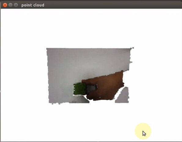
8.3.3 Program Outcome
When the game starts, the robotic arm will transform the pre-cropped point cloud data into a depth image, which is subsequently displayed in the visualization window. In the feedback display, users can examine the depth image. For different perspectives of the point cloud, users can either hold down the left mouse button or scroll to drag and navigate through the point cloud. Furthermore, scrolling the mouse wheel enables zooming in on the point cloud, providing a more detailed view.
8.3.4 Launch File Analysis
The Launch file is saved in /home/ubuntu/jetarm/src/jetarm_example/src/jetarm_6dof_rgbd_cam /launch/3_rgb_depth_image_to_point_cloud.launch
{lineno-start=}
<launch>
<include file="$(find jetarm_bringup)/launch/base.launch"/>
<node name="get_depth_rgb" pkg="jetarm_6dof_rgbd_cam" type="3_rgb_depth_image_to_point_cloud.py" output="screen" respawn="true">
</node>
</launch>
Initiate base.launch file to invoke the robot arm basic configuration.
2 | <include file="$(find jetarm_bringup)/launch/base.launch"/> |
Launch 3_rgb_depth_image_to_point_cloud.pysource code file using the node.
4 5 | <node name="get_depth_rgb" pkg="jetarm_6dof_rgbd_cam" type="3_rgb_depth_image_to_point_cloud.py" output="screen" respawn="true"> </node> |
8.3.5 Python Source Code Analysis
The source code file locates in /home/ubuntu/jetarm/src/jetarm_example/src/jetarm_6dof_rgbd_cam /scripts/3_rgb_depth_image_to_point_cloud.py
The program flowchart is as below:
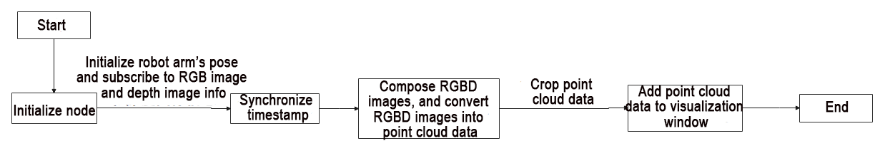
The program’s primary logic, as depicted in the diagram above, includes acquiring RGB and depth images from the camera. Subsequently, the program processes this data and employs mouse click events to measure the distance from the clicked point and determine the nearest point distance.
Import Feature Pack
Import the necessary modules using the import statements:
cv2 for OpenCV image processing.
rospy for ROS communication.
numpy for array operations.
message_filters for implementing message filtering and synchronization, particularly for handling sensor data and messages in ROS.
Import the Image message type and rename it as RosImage.
Import the SetBool service message type from the std_srvs.srv module.
Import the fps functionality module from the vision_utils module for frame rate calculation.
Use the queue module for executing queue-related operations in multithreading.
Import the ROS message type named MultiRawIdPosDur from the hiwonder_interfaces.msg module. This message type is used for defining custom ROS messages for data transmission and communication within the ROS system.
Import the servo control module from jetarm_sdk.
Import the Open3D library.
9 10 11 12 13 14 15 16 17 18 19 | import cv2 import rospy import numpy as np import message_filters from sensor_msgs.msg import Image from std_srvs.srv import SetBool from vision_utils import fps import queue from hiwonder_interfaces.msg import MultiRawIdPosDur from jetarm_sdk import pid, bus_servo_control import open3d as o3d |
Initialize the variable have_add、get_point
21 22 | haved_add = False get_point = False |
Store the point cloud to be displayed.
23 | target_cloud = o3d.geometry.PointCloud() # 要显示的点云(the point cloud to be displayed) |
Utilize cuda to accelerate the open3d program.
26 | device = o3d.core.Device('CUDA:0') |
Define Intrinsic and Extrinsic Parameters
The intrinsic and extrinsic matrices for the camera have been defined. These matrices are instrumental in converting color images and depth images into point cloud data.
29 30 31 32 33 34 35 36 | intrinsic = o3d.core.Tensor([[477, 0, 316], [0, 477, 189], [0, 0, 1]]) extrinsic = o3d.core.Tensor([[1.0, 0.0, 0.0, 0.0], [0.0, 1.0, 0.0, 0.17], [0.0, 0.0, 1.0, 0.433], [0.0, 0.0, 0.0, 1.0]]) |
Define roi Area
A matrix defining the region of interest (ROI) has been established to delineate the specific area for point cloud cropping. This matrix configures the coordinates of four vertices, with each vertex represented by a three-dimensional coordinate [x, y, z]. In this context, x corresponds to the horizontal direction, y to the vertical direction, and z is set to 0 (indicating a planar area). The data type for these coordinates is floating-point.
48 49 50 51 52 53 | roi = np.array([ [-0.05, -0.20, 0], [-0.05, -0.05, 0], [0.1, -0.05, 0], [0.1, -0.20, 0]], dtype = np.float64) |
Specify Cropping Region
We’ve created a vol object to define a specific polygonal volume. This object is responsible for specifying the cropping region, indicating the axes for cropping, and establishing the depth range for cropping.
55 | vol = o3d.visualization.SelectionPolygonVolume() |
Specifically, the cropping is carried out along the Z-axis, with a range set from -0.26 to 0.26 meters. The polygonal boundaries of the chosen volume align with the ROI area. Additionally, an intrinsic object named intrinsic has been generated for the Pinhole camera. These intrinsic parameters encompass the image’s width and height, along with the horizontal and vertical focal lengths and the principal point. These parameters will play a crucial role in transforming point cloud data from the camera coordinate system to the world coordinate system.
56 57 58 59 60 61 62 | # 裁剪z轴,范围(crop z-axis, range) vol.orthogonal_axis = 'Z' vol.axis_max = 0.26 vol.axis_min = -0.26 vol.bounding_polygon = o3d.utility.Vector3dVector(roi) intrinsic = o3d.camera.PinholeCameraIntrinsic(640, 400, 477, 477, 316, 189)#356, 260 FPS = None |
Initialize Node
Print the related info on the terminal and initialize the nodes.
110 111 112 113 114 115 116 117 118 119 120 121 | if __name__ == "__main__": print(''' ********************************************* * * * 此程序需要订阅深度摄像头节点,开启前请确保 * * 已开启摄像头节点,通过rostopic list可查看 * * 是否有usb_cam相关节点,成功运行可看到终端 * * running ... * * * ********************************************* ''') rospy.init_node('point_cloud', anonymous=True) |
Create Servo Publisher
The
servos_pubcreates a servo publisher, sending messages to the/controllers/multi_id_pos_durtopic. Here,MultiRawIdPosDuris the message type used to control the positions and durations of multiple servos.The
set_servosfunction from thebus_servo_controlmodule is utilized to set the initial position and duration of the servos. The parameters include the publisher instance, servo runtime (in milliseconds), and a tuple containing the IDs and rotation angles (ranging from 1-1000) of multiple servos.122 123 124 125
servos_pub = rospy.Publisher('/controllers/multi_id_pos_dur', MultiRawIdPosDur, queue_size=1) rospy.sleep(2) bus_servo_control.set_servos(servos_pub, 1000, ((1, 500), (2, 560), (3, 160), (4, 80), (5, 500), (10, 200))) rospy.sleep(3)
Wait for /rgbd_cam/set_ldp Service to Initiate
Create a service proxy, and use
SetBoolmessage type to specify the service request and response type.Convey
Falseto/rgbd_cam/set_ldpservice.127 128 129
rospy.wait_for_service('/rgbd_cam/set_ldp') rospy.ServiceProxy('/rgbd_cam/set_ldp', SetBool)(False) rospy.sleep(1)
Create Visualization Window
Create a window and configure the following parameters: window name (point cloud), width, height, and visibility status.
133 134 135 | # 创建可视化窗口(create a visualization window) vis = o3d.visualization.Visualizer() vis.create_window(window_name='point cloud', width=640, height=480, visible=1) |
Receive Image Info
(1) Create rgb_sub image subscriber, and use message_filters.Subscriber’ to create a message subscriber.
The first parameter /rgbd_cam/color/image_raw represents the image topic name.
The second parameter RosImage refers to the message type.
The third parameter queue_size=1 specify the size of message queue.
(2) Create depth_sub image subscriber, and use message_filters.Subscriber to create a message subscriber.
The first parameter /rgbd_cam/depth/image_raw denotes the image topic name.
The second parameter RosImage is the message type.
The third parameter queue_size=1 specifies the size of the message queue.
137 138 | rgb_sub = message_filters.Subscriber('/rgbd_cam/color/image_raw', Image) depth_sub = message_filters.Subscriber('/rgbd_cam/depth/image_raw', Image) |
multi_callback Function
63 64 65 66 67 68 69 70 71 72 73 74 75 76 77 78 79 80 81 82 83 84 85 86 87 88 89 90 91 92 93 94 95 96 97 98 99 100 101 102 103 104 105 106 107 108
def multi_callback(ros_rgb_image, ros_depth_image): global get_point, t0 try: # ros格式转为numpy(convert ros format to numpy) image_rgb = np.ndarray(shape=(ros_rgb_image.height, ros_rgb_image.width, 3), dtype=np.uint8, buffer=ros_rgb_image.data) depth_image = np.ndarray(shape=(ros_depth_image.height, ros_depth_image.width), dtype=np.uint16, buffer=ros_depth_image.data) # 统一分辨率为640x400(standardize the resolution to 640x400) image_rgb = image_rgb[40:440, ] o3d_image_rgb = o3d.geometry.Image(image_rgb) o3d_image_depth = o3d.geometry.Image(np.ascontiguousarray(depth_image)) # rgbd --> point_cloud rgbd_image = o3d.geometry.RGBDImage.create_from_color_and_depth(o3d_image_rgb, o3d_image_depth, convert_rgb_to_intensity=False) # cpu占用大 (high CPU usage) pc = o3d.geometry.PointCloud.create_from_rgbd_image(rgbd_image, intrinsic)#, extrinsic=extrinsic) ''' # numpy格式转为open3d格式(convert numpy format to open3d format) o3d_image_rgb = o3d.t.geometry.Image(o3d.core.Tensor(image_rgb, dtype=o3d.core.Dtype.UInt8, device=device)) o3d_image_depth = o3d.t.geometry.Image(o3d.core.Tensor(np.ascontiguousarray(depth_image), dtype=o3d.core.Dtype.Float32, device=device)) # rgb depth ---> rgbd rgbd = o3d.t.geometry.RGBDImage(o3d_image_rgb, o3d_image_depth) # rgbd ---> point cloud point_cloud = o3d.t.geometry.PointCloud.create_from_rgbd_image(rgbd, intrinsic)#, extrinsic) # 取出gpu的数据(retrieve data from the GPU) pc = point_cloud.to_legacy() ''' # 裁剪(crop) roi_pc = pc#vol.crop_point_cloud(pc) target_cloud.points = roi_pc.points target_cloud.colors = roi_pc.colors # 转180度方便查看(rotate 180 degrees for easier viewing) target_cloud.transform(np.asarray([[1, 0, 0, 0], [0, -1, 0, 0], [0, 0, -1, 0], [0, 0, 0, 1]])) get_point = True fps = int(1.0/(rospy.get_time() - t0)) print('\r', 'FPS: ' + str(fps), end='') except BaseException as e: print('callback error:', e) t0 = rospy.get_time()
Convert ros-Formatted Image into numpy
Arrays in NumPy, namely
image_rgbanddepth_image, have been created to store RGB and depth image data, facilitating subsequent processing of both types of images.66 67 68 69
try: # ros格式转为numpy(convert ros format to numpy) image_rgb = np.ndarray(shape=(ros_rgb_image.height, ros_rgb_image.width, 3), dtype=np.uint8, buffer=ros_rgb_image.data) depth_image = np.ndarray(shape=(ros_depth_image.height, ros_depth_image.width), dtype=np.uint16, buffer=ros_depth_image.data)
A region is cropped from the original RGB image (
rgb_image), specifically from pixel coordinates 40 rows to 440 rows.The NumPy arrays
image_rgbanddepth_imageare then converted into Open3D image objects (o3d_image_rgb). This conversion allows for processing and visualization within Open3D, establishing a foundational data basis for subsequent point cloud creation and processing.71 72 73 74
image_rgb = image_rgb[40:440, ] o3d_image_rgb = o3d.geometry.Image(image_rgb) o3d_image_depth = o3d.geometry.Image(np.ascontiguousarray(depth_image))
Generate rgbd Image
An RGB-D (Color-Depth) image object, named rgbd_image, has been created, comprising the color image (o3d_image_rgb) and the depth image (o3d_image_depth).
Within this function call, the parameter convert_rgb_to_intensity is set to False. This indicates that color information will not be converted into intensity information.
76 77 | # rgbd --> point_cloud rgbd_image = o3d.geometry.RGBDImage.create_from_color_and_depth(o3d_image_rgb, o3d_image_depth, convert_rgb_to_intensity=False) |
Convert rgbd Image into Point Cloud Data
Utilize rgbd_image and camera intrinsic parameter to generate a point cloud object.
Convert rgbd image into three dimensional point cloud data. Each point contains three dimensional coordinate information and color information.
79 | pc = o3d.geometry.PointCloud.create_from_rgbd_image(rgbd_image, intrinsic)#, extrinsic=extrinsic) |
The point cloud data from the variable pc has been assigned to roi_pc. Subsequently, the points and color data of roi_pc have been allocated to the variable target_cloud.
96 97 98 99 | roi_pc = pc#vol.crop_point_cloud(pc) target_cloud.points = roi_pc.points target_cloud.colors = roi_pc.colors |
The transform function has been invoked to perform a transformation on target_cloud, involving a rotation around both the Y-axis and Z-axis, inverting the point cloud.
100 101 | # 转180度方便查看(rotate 180 degrees for easier viewing) target_cloud.transform(np.asarray([[1, 0, 0, 0], [0, -1, 0, 0], [0, 0, -1, 0], [0, 0, 0, 1]])) |
Set get_point to True.
The frame rate is estimated by calculating the time interval between two consecutive callbacks. rospy.get_time() is used to obtain the current timestamp, and the reciprocal of the time difference between the two timestamps represents the frame rate. This frame rate, stored as an integer in the variable fps, is printed to the terminal.
103 104 105 | get_point = True fps = int(1.0/(rospy.get_time() - t0)) print('\r', 'FPS: ' + str(fps), end='') |
If the program encounters an exception, the error information is printed.
The current timestamp is stored in t0 for subsequent frame rate calculations. This way, the program continuously computes and updates frame rate information, allowing users to monitor the performance of the program in real-time.
106 107 108 | except BaseException as e: print('callback error:', e) t0 = rospy.get_time() |
Synchronize Timestamp
Establish a time synchronizer to synchronize messages from the rgb_sub and depth_sub topics. The 2 signifies a maximum buffer size of 2 messages, and 0.03 implies that messages with a timestamp difference of no more than 0.03 seconds will be considered synchronized.
140 141 | # 同步时间戳, 时间允许有误差在0.02s(synchronize timestamps, allowing for a time error of up to 0.02 seconds) sync = message_filters.ApproximateTimeSynchronizer([rgb_sub, depth_sub], 2, 0.015) |
Call the multi_callback function.
142 | sync.registerCallback(multi_callback) #执行反馈函数(execute feedback function) |
Add Point Cloud Data to Visualization Window
Check if the node is running, and if so, enter the While loop.
If haved_add is False and get_point is True, use vis.add_geometry(target_cloud) to add the point cloud data to the visualization window and set haved_add to True.
If haved_add is already True, then check if get_point is also True. If it is, it indicates that new point cloud data is ready. Perform the following actions:
set get_point to False, update the point cloud data, handle events in the visualization window using vis.poll_events(), update the renderer using vis.update_renderer().
If haved_add is still False, it means that the point cloud data has not been added to the visualization window yet. In this case, the code sleeps for a short duration (rospy.sleep(0.01)) to reduce CPU usage.
145 146 147 148 149 150 151 152 153 154 155 156 157 158 159 | while not rospy.is_shutdown(): if not haved_add and get_point: vis.add_geometry(target_cloud) haved_add = True if haved_add: if get_point: get_point = False # 刷新(refresh) vis.update_geometry(target_cloud) vis.poll_events() vis.update_renderer() else: rospy.sleep(0.001) else: rospy.sleep(0.01) |
8.4 Height Detection and Gripping
8.4.1 Program Flow
Start by initializing the node and fetching topic information related to RGB and depth images.
Then, perform image processing to determine the pixel coordinates of the tallest object within the field of view.
Afterward, convert these pixel coordinates into the world coordinates of the robotic arm through a coordinate system transformation.
Finally, conclude the process by planning the trajectory of the robotic arm for grasping and placing the large wooden block.
8.4.2 Operation Steps
Note
The input command should be case sensitive, and the keywords can be complemented using Tab key.
(1) Double-click to open the command line terminal, and execute the command below to close the auto-start service.
~/.stop_ros.sh
(2) Run the following command and hit Enter to run the game program.
roslaunch jetarm_6dof_rgbd_cam remove_too_high.launch
(3) If you need to terminate the running program, use short-cut Ctrl+C.
(4) Following the above function, it is essential to enable the app service; otherwise, the app functions may be impacted. Execute the command below to enable the app service.
sudo systemctl start start_app_node.service
(5) After the service is initiated successfully, the robot will emit a beeping sound.
8.4.3 Program Outcome
Once the game begins, place a 30x30mm block and a 40x40mm block within the recognition area on the map. Subsequently, the robotic arm will assess their heights and pick up the taller of the two.
8.4.4 Launch File Analysis
The Launch file is saved in : /home/ubuntu/jetarm/src/jetarm_example/src/jetarm_6dof_rgbd_cam /launch/remove_too_high.launch
1 2 3 4 5 6 | <launch> <include file="$(find jetarm_bringup)/launch/base.launch"/> <node name="get_depth_rgb" pkg="jetarm_6dof_rgbd_cam" type="remove_too_high.py" output="screen" respawn="true"> </node> </launch> |
Initiate base.launch file, and invoke some robot arm basic settings.
2 | <include file="$(find jetarm_bringup)/launch/base.launch"/> |
Initiate remove_too_high.py source code file using the node.
4 5 | <node name="get_depth_rgb" pkg="jetarm_6dof_rgbd_cam" type="remove_too_high.py" output="screen" respawn="true"> </node> |
8.4.5 Python Source Code Analysis
The source code file is saved in /home/ubuntu/jetarm/src/jetarm_example/src/jetarm_6dof_rgbd_cam/scripts/remove_too_high.py
The program flowchart is as below:
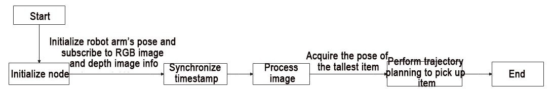
The program’s core logic, as depicted in the above diagram, revolves around obtaining RGB and depth images from the camera. Following image processing, the program then moves on to acquiring the pose of the tallest object within the field of view. Subsequently, it initiates the grasp operation to relocate the large block.
Import Feature Pack
Use import statements to bring in the necessary modules:
cv2 for OpenCV image processing.
rospy for ROS communication.
numpy for array operations.
math for mathematical calculations.
message_filters for implementing message filtering and synchronization, specifically for handling sensor data and messages in ROS.
Import the Image message type and rename it as RosImage.
Import the SetBool service message type from the std_srvs.srv module.
Import the fps functionality module from the vision_utils module for frame rate calculation.
Utilize the queue module for executing queue-related operations in multithreading.
Import the ROS message type named MultiRawIdPosDur from the hiwonder_interfaces.msg module. This type is used to define custom ROS messages for data transmission and communication within the ROS system.
Import modules from vision_utils for coordinate system transformation calculations.
Import modules such as pid, bus_servo_control, sdk_client, and tone from jetarm_sdk.
Import the library for kinematics control from jetarm_kinematics.
Import the action_group_controller for action group control.
Define a variable named CONFIG_NAME.
10 11 12 13 14 15 16 17 18 19 20 21 22 23 24 25 26 | import cv2 import rospy import numpy as np import math import message_filters import time from sensor_msgs.msg import Image as RosImage from sensor_msgs.msg import CameraInfo from std_srvs.srv import SetBool from vision_utils import fps from hiwonder_interfaces.srv import GetRobotPose import threading import queue from hiwonder_interfaces.msg import MultiRawIdPosDur from vision_utils import xyz_quat_to_mat, xyz_euler_to_mat, mat_to_xyz_euler from jetarm_sdk import pid, bus_servo_control, sdk_client, tone from jetarm_kinematics import kinematics_control |
depth_pixel_to_camera Function
This function is employed to convert pixel coordinates from the depth image into three-dimensional point coordinates within the camera coordinate system.
pixel_coords: A tuple (px, py) representing pixel coordinates in the depth image, indicating the pixel’s position.
depth: The depth value corresponding to the pixel.
intrinsics: Camera intrinsics, presented as a tuple (fx, fy, cx, cy), representing the camera’s focal lengths and optical center.
The formula is applied to calculate and return a NumPy array containing x, y, and z values, which represent the three-dimensional point coordinates.
30 31 32 33 34 35 36 | def depth_pixel_to_camera(pixel_coords, depth, intrinsics): fx, fy, cx, cy = intrinsics px, py = pixel_coords x = (px - cx) * depth / fx y = (py - cy) * depth / fy z = depth return np.array([x, y, z]) |
Initiate RgbDepthImageNode Class (RGB Depth Image Class)
Display pertinent messages in the terminal. Initiate the RgbDepthImageNode class and repeatedly invoke the node.image_proc() method within a loop until Ctrl+C is pressed or the ROS node is closed. Output the log message shutdown2 upon the conclusion of the loop.
214 215 216 217 218 219 220 221 222 223 224 225 226 227 228 229 230 231 | if __name__ == "__main__": print(''' ********************************************* * * * 此程序需要订阅深度摄像头节点,开启前请确保(The depth camera node needs to be subscribed for this program, please ensure that before starting) * * 已开启摄像头节点, 通过rostopic list可查看(The camera node has been started, please check via rostopic list) * * 是否有usb_cam相关节点,成功运行可看到终端(Whether there are usb_cam related nodes, you can see the terminal if it runs successfully) * * running ... * * * ********************************************* ''') try: node = RgbDepthImageNode() while not rospy.is_shutdown(): node.image_proc() except KeyboardInterrupt: rospy.loginfo("shutdown2") |
Initialization Function of RgbDepthImageNode Class
39 40 41 42 43 44 45 46 47 48 49 50 51 | class RgbDepthImageNode: def __init__(self): rospy.init_node('remove_too_high_node', anonymous=True) config = rospy.get_param(CONFIG_NAME) self.endpoint = None self.hand2cam_tf_matrix = config['hand2cam_tf_matrix'] self.fps = fps.FPS() self.last_shape = "none" self.moving = False self.stamp = time.time() self.count = 0 self.last_position = (0, 0, 0) self.sdk = sdk_client.JetArmSDKClient() |
Initialize remove_too_high_node node.
39 40 41 | class RgbDepthImageNode: def __init__(self): rospy.init_node('remove_too_high_node', anonymous=True) |
Initialize the related variable.
43 44 45 46 47 48 49 50 51 | self.endpoint = None self.hand2cam_tf_matrix = config['hand2cam_tf_matrix'] self.fps = fps.FPS() self.last_shape = "none" self.moving = False self.stamp = time.time() self.count = 0 self.last_position = (0, 0, 0) self.sdk = sdk_client.JetArmSDKClient() |
Create Servo Publisher
The servos_pub creates a servo publisher, sending messages to the /controllers/multi_id_pos_dur topic. Here, MultiRawIdPosDur is the message type used to control the positions and durations of multiple servos.
The set_servos function from the bus_servo_control module is utilized to set the initial position and duration of the servos. The parameters include the publisher instance, servo runtime (in milliseconds), and a tuple containing the IDs and rotation angles (ranging from 1-1000) of multiple servos.
53 54 55 56 | self.servos_pub = rospy.Publisher('/controllers/multi_id_pos_dur', MultiRawIdPosDur, queue_size=1) rospy.sleep(3) bus_servo_control.set_servos(self.servos_pub, 1000, ((1, 500), (2, 540), (3, 220), (4, 50), (5, 500), (10, 200))) rospy.sleep(2) |
Wait for /rgbd_cam/set_ldp Service to Initiate
Create a service proxy, and use SetBool message type to specify the service request and response type.
Convey False to /rgbd_cam/set_ldp service.
58 59 60 | rospy.wait_for_service('/rgbd_cam/set_ldp') rospy.ServiceProxy('/rgbd_cam/set_ldp', SetBool)(False) threading.Thread(target=self.get_endpoint, args=()).start() |
Create a new thread, and invoke get_endpoint function.
60 | threading.Thread(target=self.get_endpoint, args=()).start() |
Receive Image Information
(1) Create rgb_sub image information subscriber, and utilize message_filters.Subscriber to create a message subscriber.
The first parameter /rgbd_cam/color/image_raw represents the image topic name.
The second parameter RosImage refers to the message type.
The third parameter queue_size=1 specify the size of message queue.
(2) Create depth_sub image subscriber, and use message_filters.Subscriber to create a message subscriber.
The first parameter /rgbd_cam/depth/image_raw denotes the image topic name.
The second parameter RosImage is the message type.
The third parameter queue_size=1 specifies the size of the message queue.
(3) Create info_sub information subscriber, and utilize message_filters.Subscriber to create a message subscriber.
The first parameter /rgbd_cam/depth/camera_info denotes the camera information topic name.
The second parameter CameraInfo is the message type.
The third parameter queue_size=1 specifies the size of the message queue.
62 63 64 | rgb_sub = message_filters.Subscriber('/rgbd_cam/color/image_raw', RosImage, queue_size=1) depth_sub = message_filters.Subscriber('/rgbd_cam/depth/image_raw', RosImage, queue_size=1) info_sub = message_filters.Subscriber('/rgbd_cam/depth/camera_info', CameraInfo, queue_size=1) |
Synchronize Timestamp
Establish a time synchronizer to synchronize messages from the rgb_sub and depth_sub topics. The 3 signifies a maximum buffer size of 3 messages, and 0.03 implies that messages with a timestamp difference of no more than 0.03 seconds will be considered synchronized.
66 67 68 69 | # 同步时间戳, 时间允许有误差在0.03s(synchronize timestamps, allowing for a time error of up to 0.03 seconds) sync = message_filters.ApproximateTimeSynchronizer([rgb_sub, depth_sub, info_sub], 3, 0.03) sync.registerCallback(self.multi_callback) #执行反馈函数(execute feedback function) self.queue = queue.Queue(maxsize=1) |
get_endpoint Function
In the absence of a node shutdown signal, the program enters a While loop. Inside this loop, a rospy.ServiceProxy is established to call the /kinematics/get_current_pose service, retrieving the robot’s current pose information encompassing position and orientation. The acquired data is stored in the endpoint variable.
Subsequently, the xyz_quat_to_mat function is invoked to transform the position and orientation details from endpoint into a matrix. The outcome is then stored in the self.endpoint member variable, serving as a foundation for subsequent coordinate system transformations.
71 72 73 74 75 76 | def get_endpoint(self): while not rospy.is_shutdown(): endpoint = rospy.ServiceProxy('/kinematics/get_current_pose', GetRobotPose)().pose self.endpoint = xyz_quat_to_mat([endpoint.position.x, endpoint.position.y, endpoint.position.z], [endpoint.orientation.w, endpoint.orientation.x, endpoint.orientation.y, endpoint.orientation.z]) rospy.sleep(0.5) |
multi_callback Function
The multi_callback function receives messages from ros_rgb_image, ros_depth_image, and camera_info. It checks if self.queue is empty. If the queue is empty, it adds a tuple to the queue. This tuple contains synchronized messages of ros_rgb_image, ros_depth_image, and camera_info, indicating the successful synchronization of these three images.
117 118 119 | def multi_callback(self, ros_rgb_image, ros_depth_image, camera_info): if self.queue.empty(): self.queue.put_nowait((ros_rgb_image, ros_depth_image, camera_info)) |
Pick Function
78 79 80 81 82 83 84 85 86 87 88 89 90 91 92 93 94 95 96 97 98 99 100 101 102 103 104 105 106 107 108 109 110 111 112 113 114 | def pick(self, position, angle): angle = angle % 90 angle = angle - 90 if angle > 40 else (angle + 90 if angle < -45 else angle) print('ang', angle) position[2] += 0.05 ret = kinematics_control.set_pose_target(position, 80) if len(ret[1]) > 0: bus_servo_control.set_servos(self.servos_pub, 1500, ((1, ret[1][0]),(2, ret[1][1]), (3, ret[1][2]),(4, ret[1][3]), (5, ret[1][4]))) rospy.sleep(1.5) angle = 500 + int(1000 * (angle + ret[3][-1]) / 240) print('ret',ret) bus_servo_control.set_servos(self.servos_pub, 500, ((5, angle),)) rospy.sleep(0.5) position[2] -= 0.05 ret = kinematics_control.set_pose_target(position, 80) if len(ret[1]) > 0: bus_servo_control.set_servos(self.servos_pub, 1500, ((1, ret[1][0]),(2, ret[1][1]), (3, ret[1][2]),(4, ret[1][3]), (5, angle))) rospy.sleep(1.5) bus_servo_control.set_servos(self.servos_pub, 1000, ((10, 700),)) rospy.sleep(1) position[2] += 0.05 ret = kinematics_control.set_pose_target(position, 80) if len(ret[1]) > 0: bus_servo_control.set_servos(self.servos_pub, 1500, ((1, ret[1][0]),(2, ret[1][1]), (3, ret[1][2]),(4, ret[1][3]), (5, angle))) rospy.sleep(1.5) bus_servo_control.set_servos(self.servos_pub, 1000, ((1, 500), (2, 740), (3, 100), (4, 260), (5, 500))) rospy.sleep(1) bus_servo_control.set_servos(self.servos_pub, 1000, ((1, 150), (2, 635), (3, 100), (4, 260), (5, 500))) rospy.sleep(1) bus_servo_control.set_servos(self.servos_pub, 1000, ((1, 150), (2, 600), (3, 125), (4, 175), (5, 500))) rospy.sleep(1) bus_servo_control.set_servos(self.servos_pub, 1000, ((1, 150), (2, 600), (3, 125), (4, 175), (5, 500), (10, 200))) rospy.sleep(1) bus_servo_control.set_servos(self.servos_pub, 1000, ((1, 500), (2, 540), (3, 220), (4, 50), (5, 500), (10, 200))) rospy.sleep(2) self.stamp = time.time() self.moving = False |
Move Above The Block
Determine the rotation angle for the gripping operation, ensuring it stays within the range of ±45°.
79 80 | angle = angle % 90 angle = angle - 90 if angle > 40 else (angle + 90 if angle < -45 else angle) |
Increase the Z-axis coordinate of the target position (position) by 0.05m. Specify the gripping target position and set the pitch angle of the robotic arm to 80°.
98 99 | position[2] += 0.05 ret = kinematics_control.set_pose_target(position, 80) |
If ret[1] is not empty, employ the set_servos function to transmit information to each servo, prompting the robotic arm to move to a position 0.05m above the specified target location.
100 101 102 | if len(ret[1]) > 0: bus_servo_control.set_servos(self.servos_pub, 1500, ((1, ret[1][0]),(2, ret[1][1]), (3, ret[1][2]),(4, ret[1][3]), (5, angle))) rospy.sleep(1.5) |
Grip the Block
Compute and set the target angle of servo 5.
87 88 89 90 | angle = 500 + int(1000 * (angle + ret[3][-1]) / 240) print('ret',ret) bus_servo_control.set_servos(self.servos_pub, 500, ((5, angle),)) rospy.sleep(0.5) |
Raise the Z-axis coordinate of the target position (position) by 0.05m. Specify the gripping target position and set the pitch angle of the robotic arm to 80°.
91 92 | position[2] -= 0.05 ret = kinematics_control.set_pose_target(position, 80) |
If ret[1] is not empty, employ the set_servos function to transmit information to each servo, prompting the robotic arm to move to a position 0.05m below the target location and grip the block.
100 101 102 103 104 | if len(ret[1]) > 0: bus_servo_control.set_servos(self.servos_pub, 1500, ((1, ret[1][0]),(2, ret[1][1]), (3, ret[1][2]),(4, ret[1][3]), (5, angle))) rospy.sleep(1.5) bus_servo_control.set_servos(self.servos_pub, 1000, ((1, 500), (2, 740), (3, 100), (4, 260), (5, 500))) rospy.sleep(1) |
Put Down Block
Elevate the Z-axis coordinate of the target position (position) by 0.05m. Define the gripping target position and set the pitch angle of the robotic arm to 80°.
98 99 | position[2] += 0.05 ret = kinematics_control.set_pose_target(position, 80) |
Subsequent to gripping the wooden block, retreat by 0.05m. Employ set_servos to transmit servo control messages for the trajectory planning of the robotic arm, facilitating the placement of the wooden block at the specified location.
100 101 102 103 104 105 106 107 108 109 110 111 112 113 114 | if len(ret[1]) > 0: bus_servo_control.set_servos(self.servos_pub, 1500, ((1, ret[1][0]),(2, ret[1][1]), (3, ret[1][2]),(4, ret[1][3]), (5, angle))) rospy.sleep(1.5) bus_servo_control.set_servos(self.servos_pub, 1000, ((1, 500), (2, 740), (3, 100), (4, 260), (5, 500))) rospy.sleep(1) bus_servo_control.set_servos(self.servos_pub, 1000, ((1, 150), (2, 635), (3, 100), (4, 260), (5, 500))) rospy.sleep(1) bus_servo_control.set_servos(self.servos_pub, 1000, ((1, 150), (2, 600), (3, 125), (4, 175), (5, 500))) rospy.sleep(1) bus_servo_control.set_servos(self.servos_pub, 1000, ((1, 150), (2, 600), (3, 125), (4, 175), (5, 500), (10, 200))) rospy.sleep(1) bus_servo_control.set_servos(self.servos_pub, 1000, ((1, 500), (2, 540), (3, 220), (4, 50), (5, 500), (10, 200))) rospy.sleep(2) self.stamp = time.time() self.moving = False |
image_proc Function
Retrieve synchronized RGB images, depth images, and camera messages from the self.queue.
121 122 | def image_proc(self): ros_rgb_image, ros_depth_image, camera_info = self.queue.get(block=True) |
Create a NumPy array named rgb_image to store RGB image data. Extract data from ros_rgb_image and construct it based on the image height, width, and data type.
Create a NumPy array named depth_image to store depth image data. Extract data from ros_depth_image and construct it based on the image height and width.
Obtain camera parameters and the height and width of the depth image.
123 124 125 126 127 128 129 | try: rgb_image = np.ndarray(shape=(ros_rgb_image.height, ros_rgb_image.width, 3), dtype=np.uint8, buffer=ros_rgb_image.data) depth_image = np.ndarray(shape=(ros_depth_image.height, ros_depth_image.width), dtype=np.uint16, buffer=ros_depth_image.data) K = camera_info.K ih, iw = depth_image.shape[:2] |
Acquire Coordinate of The Smallest Depth Pixel
Create a NumPy array named rgb_image to store RGB image data. Extract data from ros_rgb_image and construct it based on the image height, width, and data type.
Create a NumPy array named depth_image to store depth image data. Extract data from ros_depth_image and construct it based on the image height and width.
Obtain camera parameters and the height and width of the depth image.
132 133 134 135 136 | depth = depth_image.copy() depth[380:400, :] = np.array([[55555,]*640]*20) depth = depth.reshape((-1, )).copy() depth[depth<=100] = 55555 min_index = np.argmin(depth) |
Calculate the row coordinate min_y of the pixel with the minimum depth value by using integer division. Divide min_index by w (image width), resulting in the row coordinate min_y. Integer division truncates the decimal part, so the result is an integer representing the row position of the pixel with the minimum depth value in the depth image.
Multiply min_y by w (image width), then subtract the result from min_index. This way, you can obtain the column coordinate min_x of the pixel with the minimum depth value.
136 137 138 | min_index = np.argmin(depth) min_y = min_index // iw min_x = min_index - min_y * iw |
Preprocess Image
Assign the values of target_point to min_x and min_y, respectively.
Use np.clip to constrain the values in the depth image between 0 and 2000; values exceeding this range will be truncated.
Convert the data type of the depth image to np.float64. Normalize the depth values to a range between 0 and 255 for subsequent visualization.
Set pixel values in the depth image greater than min_dist + 10 to 0.
Re-normalize and convert the updated depth image to a range between 0 and 255.
140 141 142 143 144 | min_dist = depth_image[min_y, min_x] sim_depth_image = np.clip(depth_image, 0, 2000).astype(np.float64) / 2000 * 255 depth_image = np.where(depth_image > min_dist + 10, 0, depth_image) sim_depth_image_sort = np.clip(depth_image, 0, 2000).astype(np.float64) / 2000 * 255 depth_gray = sim_depth_image_sort.astype(np.uint8) |
Apply Gaussian blur to the depth image for smoothing and noise reduction.
Convert the depth image to a binary image, where pixels with depth values less than 1 are set to 0, and the rest are set to 255.
Perform an erosion operation on the binary image to remove small noise or fill small holes in the image.
Dilate the eroded image to restore the shape of the original objects.
Visualize the depth image as a colored image using the JET colormap.
144 145 146 147 148 149 | depth_gray = sim_depth_image_sort.astype(np.uint8) depth_gray = cv2.GaussianBlur(depth_gray, (5, 5), 0) _, depth_bit = cv2.threshold(depth_gray, 1, 255, cv2.THRESH_BINARY) depth_bit = cv2.erode(depth_bit, np.ones((5, 5), np.uint8)) depth_bit = cv2.dilate(depth_bit, np.ones((3, 3), np.uint8)) depth_color_map = cv2.applyColorMap(sim_depth_image.astype(np.uint8), cv2.COLORMAP_JET) |
Convert Coordinate
Utilizing OpenCV to identify contours in the depth image and initializing variables to store the shape, text information, and numerical information of detected objects.
151 152 153 154 155 | contours, hierarchy = cv2.findContours(depth_bit, cv2.RETR_EXTERNAL, cv2.CHAIN_APPROX_NONE) shape = 'none' txt = "" z = 0 largest = None |
Iterating through each contour in the list of contours obtained from the cv2.findContours function using a for loop.
If the contour value is less than 500, using the cv2.minEnclosingCircle function to find the minimum enclosing circle for the contour. The returned (cx, cy) represents the center coordinates of the circle, and radius is the radius of the circle.
Drawing a red circle on the depth image with the center at (int(cx), int(cy)) and a radius of int(radius) to mark the detected object.
156 157 158 159 160 161 162 | for obj in contours: area = cv2.contourArea(obj) if area < 500 or self.moving is True: continue #cv2.drawContours(depth_color_map, obj, -1, (255, 255, 0), 4) # 绘制轮廓线(draw contour line) (cx, cy), radius = cv2.minEnclosingCircle(obj) cv2.circle(depth_color_map, (int(cx), int(cy)), int(radius), (0, 0, 255), 2) |
Using depth_pixel_to_camera to convert the pixel coordinates (cx, cy) in the depth image to a three-dimensional coordinate point position in the camera coordinate system, dividing it by 1000.0 to convert the depth value from millimeters (mm) to meters (m). (K[0], K[4], K[2], K[5]) is a tuple containing camera intrinsic parameters for coordinate transformation.
Increasing the Z coordinate of the calculated three-dimensional coordinate point position by 0.03 meters. This is done to elevate the position of the target slightly for sufficient operational space.
The np.matmul function performs matrix multiplication, multiplying self.hand2cam_tf_matrix by the coordinate transformation matrix generated by xyz_euler_to_mat to obtain pose_end, representing the end-effector relative coordinates.
Using np.matmul again to multiply self.endpoint by pose_end, transforming the end-effector relative coordinates to the robotic arm’s world coordinate system.
Extracting the pose information of the calculated robotic arm end-effector from the coordinate transformation matrix world_pose and storing it separately in pose_t (translation vector) and pose_R (rotation matrix).
164 165 166 167 168 169 | position = depth_pixel_to_camera((cx, cy), depth_image[int(cy), int(cx)] / 1000.0, (K[0], K[4], K[2], K[5])) position[2] = position[2] + 0.03 pose_end = np.matmul(self.hand2cam_tf_matrix, xyz_euler_to_mat(position, (0, 0, 0))) # 转换的末端相对坐标(relative coordinates of the converted end) world_pose = np.matmul(self.endpoint, pose_end) # 转换到机械臂世界坐标(convert to the robotic arm's world coordinates) pose_t, pose_R = mat_to_xyz_euler(world_pose) pose_t[1] += 0.01 |
Checking if the Z coordinate of the calculated object position is greater than z; if the condition is met, assigning the current contour object obj and its corresponding position information pose_t to the largest variable. Updating min_x, min_y, and txt variables.
170 171 172 173 174 | if pose_t[2] > z: largest = obj, pose_t min_x = cx min_y = cy txt = 'Dist: {}mm'.format(depth_image[int(cy), int(cx)]) |
Detect Distance from Object and Invoke Gripping Action
Check if largest is empty, calculate the distance dist between the current detected position pose_t and the last detected position self.last_position, and print the distance.
If the distance between the detected position and the previous position is less than 0.002 meters and the Z coordinate is greater than 0.009 meters, check if more than 0.5 seconds have elapsed since the last operation. If true, update the timestamp self.stamp and perform the following actions:
Assign cv2.minAreaRect(obj) to ret and set self.moving to True.
Create a new thread, invoke the self.pick method, and pass the object’s position pose_t and rotation angle rect[2] as parameters. Format the X, Y, Z coordinates of the object’s position into a string and store it in the txt variable.
If the above conditions are not met, update the timestamp self.stamp to the current time.
176 177 178 179 180 181 182 183 184 185 186 187 188 189 | if largest is not None: obj, pose_t = largest dist = math.sqrt((self.last_position[0] - pose_t[0]) ** 2 + (self.last_position[1] - pose_t[1])** 2 + (self.last_position[2] - pose_t[2])**2) print(dist) self.last_position = pose_t if dist < 0.002 and pose_t[2] > 0.009: if time.time() - self.stamp > 0.5: self.stamp = time.time() rect = cv2.minAreaRect(obj) self.moving = True threading.Thread(target=self.pick, args=(pose_t, rect[2])).start() txt = 'X:{:.3f} Y:{:.3f} Z:{:.3f}'.format(pose_t[0], pose_t[1], pose_t[2]) else: self.stamp = time.time() |
Mark the Position of Depth Value on Depth Pseudocolored Image
Draw a filled black circle and a smaller white circle on the depth pseudocolored image, marking the position of the minimum depth value. The parameters correspond to the processed image name, center coordinates, circle radius, circle color, and -1 indicating filling the entire circle. The white circle is slightly smaller than the black circle to serve as a marker.
Display text indicating the depth values on the depth pseudocolored image, with a larger black text and a slightly offset smaller gray text. The parameters correspond to the processed image, text content, starting position, font, size, color, line width, and -1 indicating antialiased line drawing mode for smoother lines.
190 191 192 193 194 | self.last_shape = shape cv2.circle(depth_color_map, (int(min_x), int(min_y)), 8, (32, 32, 32), -1) cv2.circle(depth_color_map, (int(min_x), int(min_y)), 6, (255, 255, 255), -1) cv2.putText(depth_color_map, txt, (11, ih-20), cv2.FONT_HERSHEY_PLAIN, 2.0, (32, 32, 32), 6, cv2.LINE_AA) cv2.putText(depth_color_map, txt, (10, ih-20), cv2.FONT_HERSHEY_PLAIN, 2.0, (240, 240, 240), 2, cv2.LINE_AA) |
Mark the Position of Depth Value on BGR Image
Crop a region from the original RGB image rgb_image, specifically the portion between pixel coordinates 40 rows to 440 rows. Subsequently, convert the cropped RGB image to the BGR color space.
Display text indicating the depth values on the BGR image, with a larger black text and a slightly offset smaller gray text. The parameters correspond to the processed image, text content, starting position, font, size, color, line width, and -1 indicating antialiased line drawing mode for smoother lines.
196 197 198 199 200 201 202 | bgr_image = cv2.cvtColor(rgb_image[40:440, ], cv2.COLOR_RGB2BGR) #cv2.circle(bgr_image, (int(min_x), int(min_y)), 8, (32, 32, 32), -1) #cv2.circle(bgr_image, (int(min_x), int(min_y)), 6, (255, 255, 255), -1) cv2.putText(bgr_image, txt, (11, ih - 20), cv2.FONT_HERSHEY_PLAIN, 2.0, (32, 32, 32), 6, cv2.LINE_AA) cv2.putText(bgr_image, txt, (10, ih - 20), cv2.FONT_HERSHEY_PLAIN, 2.0, (240, 240, 240), 2, cv2.LINE_AA) self.fps.update() |
Update image frame rate.
202 | self.fps.update() |
Concatenate the RGB image and the pseudocolored depth image horizontally to create a single image.
Display the final image on the depth window using cv2.imshow.
204 205 | result_image = np.concatenate([bgr_image, depth_color_map], axis=1) cv2.imshow("depth", result_image) |
Check for any keyboard input, and if a key is pressed, close the node.
208 209 | if key != -1: rospy.signal_shutdown('shutdown1') |
In the case of an exception in the code, capture and log the exception information as an error in the ROS log.
211 212 | except Exception as e: rospy.logerr('callback error:', str(e)) |
8.5 3D Space Gripping
8.5.1 Program Flow
Firstly, initialize the node and obtain the topic message of the RGB image and depth image.
Next, process the image to obtain the coordinate of the target pixel so as to track the target.
Subsequently, convert the obtained pixel coordinate into the robot arm world coordinate.
Lastly, plan the trajectory for the robot arm enabling the robot arm to place the item to corresponding position.
8.5.2 Operation Steps
Note
The input command should be case sensitive, and the keywords can be complemented using Tab key.
(1) Double-click to open the command-line terminal, and execute the following command to disable the auto-start service.
~/.stop_ros.sh
(2) Run the command and hit Enter to run the game program.
roslaunch jetarm_6dof_rgbd_cam track_and_grab.launch
(3) If you need to terminate the running program, use short-cut Ctrl+C.
(4) After completing the game experience, you must start the app service (if not started, it will affect the functionality of subsequent app features). In the terminal interface, enter the following command and press Enter to start the APP service:
sudo systemctl start start_app_node.service
(5) Once the service is started, the robotic arm will return to its initial position, and the buzzer will emit a beep.
8.5.3 Program Outcome
Upon initiating the game, the robot arm will align the camera to face forward for detecting the colored block (the program defaults to recognizing the red color). Subsequently, the camera initiates tracking of the item. Once the item’s pose is acquired, the robot arm proceeds to pick it up and relocate it to the designated position.
Note
If the item is placed within the minimal detection range, the camera cannot measure the item’s distance. In this scenario, the measurement result will be set to 0, and the terminal will display TOO CLOSE !!!. To resolve this issue, ensure the target block is positioned away from the camera for proper gripping.
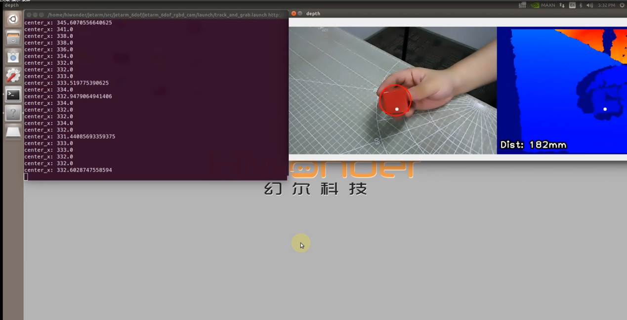
8.5.4 Launch File Analysis
Launch file is saved in /home/ubuntu/jetarm/src/jetarm_example/src/jetarm_6dof_rgbd_cam /launch/track_and_grab.launch
1 2 3 4 5 6 7 8 | <launch> <arg name="target_color" default="red" /> <include file="$(find jetarm_bringup)/launch/base.launch"/> <node name="track_and_grab" pkg="jetarm_6dof_rgbd_cam" type="track_and_grab.py" output="screen" respawn="true"> <param name="target_color" value="$(arg target_color)" /> </node> </launch> |
Set the target color to red for example.
2 | <arg name="target_color" default="red" /> |
Launch the base.launch file, and invoke the robot arm basic settings.
3 | <include file="$(find jetarm_bringup)/launch/base.launch"/> |
Launch track_and_grab.py source code using the node.
5 6 7 | <node name="track_and_grab" pkg="jetarm_6dof_rgbd_cam" type="track_and_grab.py" output="screen" respawn="true"> <param name="target_color" value="$(arg target_color)" /> </node> |
8.5.5 Python Source Code Analysis
The source code file is saved in /home/ubuntu/jetarm/src/jetarm_example/src/jetarm_6dof/jetarm_6dof_rgbd_cam /scripts/track_and_grab.py
The program flowchart is as below:
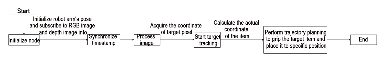
As depicted in the above diagram, the logical flow of the program primarily involves obtaining RGB and depth images from the camera, synchronizing their timestamps, processing the acquired images, tracking the target based on pixel coordinates, calculating the actual object position when the target comes to a halt, and employing trajectory planning for grasping and placing the object.
Import Feature Pack
Import the required modules through import statements:
cv2 for OpenCV image processing.
rospy for ROS communication.
numpy for array operations.
math for mathematical calculations.
message_filters for implementing message filtering and synchronization, crucial for handling sensor data and messages in ROS.
Import the Image message type and rename it as RosImage.
Import the SetBool service message type from the std_srvs.srv module.
Import the fps function module from the vision_utils module for calculating frame rates.
Use the queue module for executing queue-related operations in a multi-threaded context.
Import the MultiRawIdPosDur ROS message type from the hiwonder_interfaces.msg module. This type is utilized for defining custom ROS messages, facilitating data transmission and communication within the ROS system.
Import the necessary modules for coordinate system transformation from the vision_utils module.
Import the pid, bus_servo_control, sdk_client, and tone modules from the jetarm_sdk module.
Import the library for kinematic control from the jetarm_kinematics module.
Define a variable named CONFIG_NAME.
7 8 9 10 11 12 13 14 15 16 17 18 19 20 21 22 23 24 25 26 27 28 29 | import os import cv2 import rospy import numpy as np import threading import math import time from sensor_msgs.msg import Image as RosImage from sensor_msgs.msg import CameraInfo from visualization_msgs.msg import Marker from hiwonder_interfaces.msg import MultiRawIdPosDur from hiwonder_interfaces.srv import GetRobotPose from vision_utils import fps, colors, get_area_max_contour from vision_utils import xyz_quat_to_mat, xyz_euler_to_mat, pixels_to_world, box_center, mat_to_xyz_euler, distance, extristric_plane_shift from jetarm_sdk import pid, bus_servo_control, common import message_filters from jetarm_kinematics import kinematics_control from sensor_msgs.msg import Image as RosImage from geometry_msgs.msg import PoseStamped from std_srvs.srv import SetBool import queue CONFIG_NAME="/config" |
depth_pixel_to_camera Function
Function for converting pixel coordinates from the depth image to three-dimensional coordinates in the camera coordinate system.
pixel_coords: Pixel coordinates in the depth image, represented as a tuple (px, py), indicating the pixel’s position in the depth image.
depth: Depth value corresponding to the pixel.
intrinsics: Camera intrinsics, a tuple containing (fx, fy, cx, cy), representing the camera’s focal length and optical center.
The function calculates the three-dimensional point coordinates (x, y, z) using a formula and returns a NumPy array containing these values.
31 32 33 34 35 36 37 | def depth_pixel_to_camera(pixel_coords, depth, intrinsics): fx, fy, cx, cy = intrinsics px, py = pixel_coords x = (px - cx) * depth / fx y = (py - cy) * depth / fy z = depth return np.array([x, y, z]) |
Initiate TrackAndGrapNode Class (Tracking and Gripping Class)
Print relevant prompt messages in the terminal. Initiate the RgbDepthImageNode class, and within the loop, call the node.image_proc() method until Ctrl+C is pressed or the ROS node is closed, then output the log information shutdown2.
328 329 330 331 332 333 334 335 336 337 338 339 340 341 342 343 344 345 | if __name__ == "__main__": print(''' ********************************************* * * * 此程序需要订阅深度相机节点,开启前请确保已(before starting this program, make sure to subscribe to the depth camera node) * * 开启摄像头节点, 通过rostopic list可查看是看(the camera node has been started, you can verify this by using "rostopic list") * * 否有rgbd_cam相关节点,成功运行可看到终端(is there a rgbd_cam related node? You should see the terminal output upon successful execution) * * running ... * * * ********************************************* ''') try: node = TrackAndGrapNode() while not rospy.is_shutdown(): node.image_proc() except KeyboardInterrupt: rospy.loginfo("shutdown2") |
Initialization Function of RgbDepthImageNode Class
Initialize track_and_grap node.
106 107 108 | class TrackAndGrapNode: def __init__(self): rospy.init_node("track_and_grap", anonymous=True, log_level=rospy.INFO) |
Initialize the related variable.
109 110 111 112 113 114 115 116 117 | self.fps = fps.FPS() self.moving = False self.last_pitch_yaw = (0, 0) self.first_time = time.time() self.enable_disp = rospy.get_param('~enable_disp', True) self.color_ranges = rospy.get_param('/config/lab', {}) self.last_position = (0, 0, 0) self.stamp = time.time() |
Create Servo Publisher
The servos_pub creates a servo publisher, sending messages to the /controllers/multi_id_pos_dur topic. Here, MultiRawIdPosDur is the message type used to control the positions and durations of multiple servos.
The set_servos function from the bus_servo_control module is utilized to set the initial position and duration of the servos. The parameters include the publisher instance, servo runtime (in milliseconds), and a tuple containing the IDs and rotation angles (ranging from 1-1000) of multiple servos.
118 119 120 121 | self.servos_pub = rospy.Publisher('/controllers/multi_id_pos_dur', MultiRawIdPosDur, queue_size=1) rospy.sleep(3) bus_servo_control.set_servos(self.servos_pub, 1000, ((1, 500), (2, 720), (3, 100), (4, 120), (5, 500), (10, 200))) rospy.sleep(2) |
Retrieve the parameter named CONFIG_NAME from the ROS Parameter Server using rospy.get_param, and store it in the config variable. Subsequently, extract the parameter named hand2cam_tf_matrix from the config variable and store it in self.hand2cam_tf_matrix for subsequent use in the class methods.
123 124 | config = rospy.get_param(CONFIG_NAME) self.hand2cam_tf_matrix = config['hand2cam_tf_matrix'] |
(1) Set target_colorto red, and print the information of the tracked target.
(2) Create a color tracker named self.tracker. Utilize the self.target_color parameter obtained in the last line to initialize the color tracker.
(3) Call the color processing class and configure the tracked target.
(4) Use rospy.wait_for_service function to wait for the /rgbd_cam/set_ldp service to initiate.
126 127 128 129 | self.target_color = rospy.get_param('~target_color', 'red') rospy.loginfo("正在设置将要追踪的目标认识为" + self.target_color) self.tracker = ColorTracker(self.target_color) rospy.wait_for_service('/rgbd_cam/set_ldp') |
Color Processing Class
(1) Configure the tracking color with the provided parameter target_color.
(2) Set the values of the PID controllers for yaw (pitch angle) and pitch (rotation angle).
(3) Set the initial values for the yaw (pitch angle) and pitch (rotation angle) of the robotic arm.
40 41 42 43 44 45 46 | class ColorTracker: def __init__(self, target_color): self.target_color = target_color self.pid_yaw = pid.PID(20.5, 1.0, 1.2) self.pid_pitch = pid.PID(20.5, 1.0, 1.2) self.yaw = 500 self.pitch = 150 |
Image Processing and Tracking Function porc
(1) Initialize image.
48 49 50 51 52 | def proc (self, source_image, result_image, color_ranges): h, w = source_image.shape[:2] color = color_ranges[self.target_color] img = cv2.resize(source_image, (int(w/2), int(h/2))) |
Obtain the height and width of the image.
Obtain the color threshold of the tracked color from color_ranges.
Adjust the image size and scale both its height and width by half.
(2) Apply Gaussian blur to the image using the GaussianBlur() function from the cv2 library to filter out noise.
The first parameter img is the input image that has already been resized.
The second parameter (3, 3) specifies the size of the Gaussian convolution kernel, where both the height and width of the kernel must be positive and odd.
The third parameter 3 indicates the standard deviation of the Gaussian kernel in the horizontal direction.
53 | img_blur = cv2.GaussianBlur(img, (3, 3), 3) # 高斯模糊(Gaussian blur) |
(3) Convert the RGB color space into LAB color space.
54 | img_lab = cv2.cvtColor(img_blur, cv2.COLOR_RGB2LAB) # 转换到 LAB 空间(convert to the LAB space) |
(4) Perform thresholding, and utilize inRange() function in cv2 library to apply the thresholding processing on the image.
55 | mask = cv2.inRange(img_lab, tuple(color['min']), tuple(color['max'])) # 二值化(binarization) |
(5) Implement erosion and dilation operations on the image to smooth the contours and facilitate the subsequent search for target contours.
57 58 59 | # 平滑边缘,去除小块,合并靠近的块(smooth edges, remove small blocks, and merge adjacent blocks) eroded = cv2.erode(mask, cv2.getStructuringElement(cv2.MORPH_RECT, (3, 3))) dilated = cv2.dilate(eroded, cv2.getStructuringElement(cv2.MORPH_RECT, (3, 3))) |
The erode() function is utilized for image erosion. In the provided code eroded = cv2.erode(mask, cv2.getStructuringElement(cv2.MORPH_RECT, (3, 3))), the parameters in the parentheses are explained as follows:
The first parameter mask represents the input image.
The second parameter cv2.getStructuringElement(cv2.MORPH_RECT, (3, 3)) determines the nature of the operation, serving as the structuring element or kernel. Within the parentheses, the first parameter denotes the kernel shape, while the second parameter specifies the kernel size.
The dilate() function is employed for image dilation. The parameters inside the parentheses have the same meanings as those in the erode() function.
(6) Retrieve the contour with the maximum area by invoking the findContours() function from the cv2 library. This function is used to locate the largest contour corresponding to the color identified as the target in the image.
61 62 63 | # 找出最大轮廓(find out the largest contour) contours = cv2.findContours(dilated, cv2.RETR_EXTERNAL, cv2.CHAIN_APPROX_NONE)[-2] #max_contour_area = get_area_max_contour(contours, 10) |
The first parameter dilatedrepresents the input image.
The second parameter cv2.RETR_EXTERNAL is contour retrieving mode.
The third parameter cv2.CHAIN_APPROX_NONE is contour approximation method.
(7) Circle the tracked target.
76 77 78 79 80 81 | if min_c is not None: (center_x, center_y), radius = cv2.minEnclosingCircle(min_c[0]) # 最小外接圆(the minimum circumcircle) # 圈出识别的的要追踪的色块(outline the identified color blocks to be tracked) circle_color = colors.rgb[self.target_color] if self.target_color in colors.rgb else (0x55, 0x55, 0x55) cv2.circle(result_image, (int(center_x * 2), int(center_y * 2)), int(radius * 2), circle_color, 2) |
(8) Update PID data by applying the PID algorithm to refresh the coordinates along the X and Y axes.
83 84 85 86 87 88 89 90 91 92 93 94 95 96 97 98 99 100 101 102 | center_x = center_x * 2 center_x_1 = center_x / w if abs(center_x_1 - 0.5) > 0.02: # 相差范围小于一定值就不用再动了(if the difference range is smaller than a certain value, there's no need to move anymore) self.pid_yaw.SetPoint = 0.5 # 我们的目标是要让色块在画面的中心, 就是整个画面的像素宽度的 1/2 位置(our goal is to make the color block appear in the center of the frame, which is at half the pixel width of the entire frame) self.pid_yaw.update(center_x_1) self.yaw = min(max(self.yaw + self.pid_yaw.output, 0), 1000) else: self.pid_yaw.clear() # 如果已经到达中心了就复位一下 pid 控制器(if it has already reached the center, reset the PID controller) center_y = center_y * 2 center_y_1 = center_y / h if abs(center_y_1 - 0.5) > 0.02: self.pid_pitch.SetPoint = 0.5 self.pid_pitch.update(center_y_1) self.pitch = min(max(self.pitch + self.pid_pitch.output, 100), 720) else: self.pid_pitch.clear() # rospy.loginfo("x:{:.2f}\ty:{:.2f}".format(self.x , self.y)) return (result_image, (self.pitch, self.yaw), (center_x, center_y), radius * 2) else: |
When the x-axis coordinate of the center point of the target color (center_x) minus the x-axis coordinate of the screen center (0.5) is greater than 0.02, it means the target is not at the center of the screen. When it is less than 0.02, it indicates that the target is at the center of the screen.
If the target is not at the center of the screen, adjust the yaw angle (ID4) of the robotic arm using the pid_yaw. After the adjustment, output the value of self.yaw using the function min(max(self.yaw + self.pid_yaw.output, 0), 1000), which sets the yaw angle to be between 0 and 1000. This is achieved by taking the maximum value between the target value and 0, and then the minimum value between the target value and 1000.
If the target is at the center of the screen, reset the PID controller directly using the clear() function. The same logic applies to the pitch angle.
(9) Return the image info, and the offset of pitch angle and yaw angle.
103 | return (result_image, None, None, 0) |
Receive Image Info
(1) Create rgb_sub image subscriber, and use message_filters.Subscriber to create a message subscriber.
The first parameter /rgbd_cam/color/image_raw represents the image topic name.
The second parameter RosImage refers to the message type.
The third parameter queue_size=1 specify the size of message queue.
(2) Create depth_sub image subscriber, and use message_filters.Subscribe to create a message subscriber.
The first parameter, /rgbd_cam/depth/image_raw, denotes the topic name for the image.
The second parameter specifies the message type as RosImage.
The third parameter, queue_size=1 ,specifies the size of the message queue.
(3) Create info_sub image subscriber, and use message_filters.Subscriber to create an image subscriber.
The first parameter /rgbd_cam/depth/camera_info represents the image topic name.
The second parameter CameraInfo is the message type.
The third parameter queue_size=1 specifies the size of the message queue.
136 137 138 | rgb_sub = message_filters.Subscriber('/rgbd_cam/color/image_raw', RosImage, queue_size=1) depth_sub = message_filters.Subscriber('/rgbd_cam/depth/image_raw', RosImage, queue_size=1) info_sub = message_filters.Subscriber('/rgbd_cam/depth/camera_info', CameraInfo, queue_size=1) |
Synchronize Timestamp
Establish a time synchronizer to synchronize messages from the rgb_sub and depth_sub topics. The 3 signifies a maximum buffer size of 3 messages, and 0.03 implies that messages with a timestamp difference of no more than 0.03 seconds will be considered synchronized.
142 143 144 145 146 147 148 | # 同步时间戳, 时间允许有误差在0.03s(synchronize timestamps, allowing for a time error of up to 0.03 seconds) sync = message_filters.ApproximateTimeSynchronizer([rgb_sub, depth_sub, info_sub], 3, 0.03) sync.registerCallback(self.multi_callback) #执行反馈函数(execute feedback function) self.queue = queue.Queue(maxsize=1) self.endpoint = None self.ttt = time.time() + 10 common.loginfo("TrackAndGrapNode initailized") |
multi_callback Feedback Function
The multi_callback receives messages from ros_rgb_image, ros_depth_image, and camera_info. It checks if self.queue is empty. If the queue is empty, it places a tuple containing synchronized ros_rgb_image, ros_depth_image, and camera_info into the queue. This tuple signifies the successful synchronization of the three images.
150 151 152 | def multi_callback(self, ros_rgb_image, ros_depth_image, depth_camera_info): if self.queue.empty(): self.queue.put_nowait((ros_rgb_image, ros_depth_image, depth_camera_info)) |
get_endpoint Function
If the node shutdown signal is not received, the code enters a while loop. It creates a rospy.ServiceProxy to call the /kinematics/get_current_pose service, obtaining the current pose information of the robot, including position and orientation, which is then stored in the endpoint variable. The xyz_quat_to_mat function is then invoked to convert the position and orientation information in endpoint into a matrix, and the result is stored in the self.endpoint member variable for subsequent coordinate transformations.
154 155 156 157 158 | def get_endpoint(self): endpoint = rospy.ServiceProxy('/kinematics/get_current_pose', GetRobotPose)().pose self.endpoint = xyz_quat_to_mat([endpoint.position.x, endpoint.position.y, endpoint.position.z], [endpoint.orientation.w, endpoint.orientation.x, endpoint.orientation.y, endpoint.orientation.z]) return self.endpoint |
Gripping & Placing Function
160 161 162 163 164 165 166 167 168 169 170 171 172 173 174 175 176 177 178 179 180 181 182 183 184 185 186 187 188 189 190 191 192 193 | def pick(self, position): ret = kinematics_control.set_pose_target(position, 30) if len(ret[1]) > 0: bus_servo_control.set_servos(self.servos_pub, 1000, ((1, ret[1][0]), )) rospy.sleep(1) bus_servo_control.set_servos(self.servos_pub, 1500, ((1, ret[1][0]),(2, ret[1][1]), (3, ret[1][2]),(4, ret[1][3]), (5, ret[1][4]))) rospy.sleep(1.5) bus_servo_control.set_servos(self.servos_pub, 500, ((10, 700),)) rospy.sleep(1) position[2] += 0.03 ret = kinematics_control.set_pose_target(position, 30) if len(ret[1]) > 0: bus_servo_control.set_servos(self.servos_pub, 1000, ((1, ret[1][0]),(2, ret[1][1]), (3, ret[1][2]),(4, ret[1][3]), (5, ret[1][4]))) rospy.sleep(1) bus_servo_control.set_servos(self.servos_pub, 1000, ((1, 500), (2, 720), (3, 100), (4, 120), (5, 500), (10, 700))) rospy.sleep(1) bus_servo_control.set_servos(self.servos_pub, 1000, ((1, 125), (2, 635), (3, 120), (4, 200), (5, 500))) rospy.sleep(1) bus_servo_control.set_servos(self.servos_pub, 500, ((1, 125), (2, 550), (3, 120), (4, 150), (5, 500))) rospy.sleep(0.5) bus_servo_control.set_servos(self.servos_pub, 1000, ((1, 125), (2, 550), (3, 120), (4, 170), (5, 500), (10, 200))) rospy.sleep(1) #bus_servo_control.set_servos(self.servos_pub, 1000, ((1, 125), (2, 720), (3, 120), (4, 170), (5, 500), (10, 200))) #rospy.sleep(1) bus_servo_control.set_servos(self.servos_pub, 1000, ((1, 500), (2, 720), (3, 100), (4, 150), (5, 500), (10, 200))) rospy.sleep(2) self.tracker.yaw = 500 self.tracker.pitch = 150 self.tracker.pid_yaw.clear() self.tracker.pid_pitch.clear() self.stamp = time.time() self.first_time = time.time() + 2 self.moving = False |
(1) Obtain the inverse kinematics solution by utilizing kinematics_control.set_pose_target to achieve the target position of the colored block, storing it in the ret variable.
161 | ret = kinematics_control.set_pose_target(position, 30) |
(2) If the length of the second element in the ret variable is greater than 0, pass the obtained inverse kinematics solution to the bus_servo_control.set_servos function, controlling the robotic arm to grasp the colored block.
162 163 164 165 166 | if len(ret[1]) > 0: bus_servo_control.set_servos(self.servos_pub, 1000, ((1, ret[1][0]), )) rospy.sleep(1) bus_servo_control.set_servos(self.servos_pub, 1500, ((1, ret[1][0]),(2, ret[1][1]), (3, ret[1][2]),(4, ret[1][3]), (5, ret[1][4]))) rospy.sleep(1.5) |
(3) For placing the colored block, perform trajectory planning by setting the pulse widths for each servo in the bus_servo_control.set_servos function, guiding the robotic arm to position the block at the target location.
175 176 177 178 179 180 181 182 183 184 185 186 | bus_servo_control.set_servos(self.servos_pub, 1000, ((1, 500), (2, 720), (3, 100), (4, 120), (5, 500), (10, 700))) rospy.sleep(1) bus_servo_control.set_servos(self.servos_pub, 1000, ((1, 125), (2, 635), (3, 120), (4, 200), (5, 500))) rospy.sleep(1) bus_servo_control.set_servos(self.servos_pub, 500, ((1, 125), (2, 550), (3, 120), (4, 150), (5, 500))) rospy.sleep(0.5) bus_servo_control.set_servos(self.servos_pub, 1000, ((1, 125), (2, 550), (3, 120), (4, 170), (5, 500), (10, 200))) rospy.sleep(1) #bus_servo_control.set_servos(self.servos_pub, 1000, ((1, 125), (2, 720), (3, 120), (4, 170), (5, 500), (10, 200))) #rospy.sleep(1) bus_servo_control.set_servos(self.servos_pub, 1000, ((1, 500), (2, 720), (3, 100), (4, 150), (5, 500), (10, 200))) rospy.sleep(2) |
(4) Set the yaw (yaw angle) of the self.tracker object to 500.
(5) Set the pitch (pitch angle) of the self.tracker object to 260.
(6) Invoke the clear() method on the pid_yaw attribute of the self.tracker object to clear control parameters or variables related to yaw.
(7) Clear control parameters or variables related to pitch by calling the clear() method on the pid_pitch attribute of the self.tracker object.
(8) Set the self.stamp variable to the current timestamp, obtained using the time.time() function, for time recording purposes.
187 188 189 190 191 192 193 | self.tracker.yaw = 500 self.tracker.pitch = 150 self.tracker.pid_yaw.clear() self.tracker.pid_pitch.clear() self.stamp = time.time() self.first_time = time.time() + 2 self.moving = False |
image_process Function
Obtain the synchronized RGB image and depth image from the self.queue queue.
195 196 | def image_proc(self): ros_rgb_image, ros_depth_image, depth_camera_info = self.queue.get(block=True) |
A NumPy array named rgb_image is created to store RGB image data. Data is extracted from ros_rgb_image, and the array is constructed based on image height, width, and data type.
Similarly, a NumPy array named depth_image is created to store depth image data. Data is extracted from ros_depth_image, and the array is constructed based on image height and width.
Image data is copied from rgb_image to create result_image.
The height and width of the depth image are obtained.
197 198 199 200 201 202 | try: rgb_image = np.ndarray(shape=(ros_rgb_image.height, ros_rgb_image.width, 3), dtype=np.uint8, buffer=ros_rgb_image.data)[40:440,] depth_image = np.ndarray(shape=(ros_depth_image.height, ros_depth_image.width), dtype=np.uint16, buffer=ros_depth_image.data) result_image = np.copy(rgb_image) h, w = depth_image.shape[:2] |
Convert Depth Image into Color Depth Image
(1) Replace pixels with depth values less than or equal to 0 with 55555 to mark invalid depth values.
(2) Restrict the depth values in the depth image to the range of 0 to 2000 and convert their data type to float64. This is done to map the depth values to a specific range for visualization.
(3) Map the depth values to the range of 0 to 255 to create a colored depth map.
(4) Convert rgb_image from the RGB color space to the BGR color space. Utilize the cv2.applyColorMap function from OpenCV to apply the mapped depth values as a colored depth map using the JET color mapping. The result is stored in depth_color_map.
203 204 205 206 207 208 209 210 211 | depth = np.copy(depth_image).reshape((-1, )) depth[depth<=0] = 55555 sim_depth_image = np.clip(depth_image, 0, 2000).astype(np.float64) sim_depth_image = sim_depth_image / 2000.0 * 255.0 bgr_image = cv2.cvtColor(rgb_image, cv2.COLOR_RGB2BGR) depth_color_map = cv2.applyColorMap(sim_depth_image.astype(np.uint8), cv2.COLORMAP_JET) |
Determine Whether The Target is Tracked
Firstly, check for the availability of the target tracker self.tracker and ensure that the robotic arm self.moving is not in motion. Invoke the proc method of the target tracker to process the colored image. Return the updated image result_image, the position information of the target p_y, the center coordinates of the target center, and the radius of the target r.
213 214 | if self.tracker is not None and self.moving == False and time.time() > self.ttt: result_image, p_y, center, r = self.tracker.proc(rgb_image, result_image, self.color_ranges) |
Track the Target and Acquire Coordinate of Target Center
Check if the position information p_y of the target is not None. If the target is successfully tracked, perform the following operations:
(1) Call the set_servos method of the bus_servo_control object to control the angles of the servos. Set the angle of servo 1 to p_y[1] and the angle of servo 4 to p_y[0].
(2) Calculate center_x and center_y: Make minor adjustments to the coordinates of the target’s center, moving the target’s center 5 pixels to the right and (r - 20) pixels up. Then, check if center_x and center_y exceed the boundaries of the image. If they do, restrict them to the maximum size of the image, which is (639, 399). Print the x-coordinate of the target’s center for debugging purposes.
215 216 217 218 219 220 221 222 223 224 225 | if p_y is not None: bus_servo_control.set_servos(self.servos_pub, 20, ((1, p_y[1]), (4, p_y[0]))) # print(p_y) center_x, center_y = center center_x += 5 center_y += r - 20 if center_x > 639: center_x = 639 if center_y > 399: center_y = 399 #print("center_x:", center_x) |
Control Robotic Arm to Move Towards the Target Object and Perform the Grasping Operation
Check if the current target position p_y and the deviation from the previously recorded position self.last_pitch_yaw are both less than 1. If the deviations are small, indicating little change in the target’s position, perform the following steps:
If the time elapsed since the last action is more than 2 seconds, execute the following:
Update the timestamp: self.stamp = time.time() to record the current time.
Get the depth information of the target from the depth image: dist = depth_image[int(center_y), int(center_x)] / 1000.0 and convert it to meters.
Compensate for depth information: dist += 0.015, a small adjustment typically caused by the object’s radius.
Retrieve the intrinsic matrix K of the depth camera: K = depth_camera_info.K.
Call the get_endpoint method to obtain the position of the robotic arm’s end effector.
Use the depth_pixel_to_camera method to transform the target’s image coordinates (center_x, center_y), depth information dist, and the intrinsic matrix of the depth camera (K[0], K[4], K[2], K[5]) into coordinates in the camera coordinate system, denoted as position.
Adjust the X-axis coordinate slightly: position[0] -= 0.01, reducing it by 0.01 meters to account for a 1cm offset between the RGB and depth cameras.
Transform the coordinates position and pose (0, 0, 0) into the end effector’s relative coordinates: pose_end using the xyz_euler_to_mat method.
Multiply pose_end by the transformation matrix of the robotic arm’s world coordinates to obtain the end effector’s position in the robotic arm’s world coordinate system: world_pose.
Convert world_pose into position pose_t and orientation pose_R using the mat_to_xyz_euler method.
Make slight adjustments to pose_t, including displacements in the X, Y, and Z-axis coordinates.
Adjust the Y-axis coordinate: pose_t[1] = pose_t[1] * factor_y, considering deviations from the central line to maintain the robotic arm’s posture.
Compensate for the Z-axis coordinate height, accounting for gravity effects. The code uses linear compensation: no height compensation when the end effector is less than 0.2 meters from the center of the robotic arm. Beyond 0.2 meters, the greater the distance, the more height compensation is applied, regulated by the factor_z parameter.
Set the robotic arm state to moving: self.moving = True.
Use a thread to execute the self.pick method, passing the position pose_t as a parameter to perform the grasping operation.
Finally, print the robotic arm’s pose information as a string to the console for debugging.
226 227 228 229 230 231 232 233 234 235 236 237 238 239 240 241 242 243 244 245 246 247 | if abs(self.last_pitch_yaw[0] - p_y[0]) < 5 and abs(self.last_pitch_yaw[1] - p_y[1]) < 5: if time.time() - self.stamp > 2: self.stamp = time.time() dist = depth_image[int(center_y),int(center_x)]/1000.0 dist += 0.015 # 物体半径补偿(object radius compensation) K = depth_camera_info.K self.get_endpoint() position = depth_pixel_to_camera((center_x, center_y), dist, (K[0], K[4], K[2], K[5])) position[0] -= 0.01 # rgb相机和深度相机tf有1cm偏移(the RGB camera and the depth camera have a 1cm offset in their transforms) pose_end = np.matmul(self.hand2cam_tf_matrix, xyz_euler_to_mat(position, (0, 0, 0))) # 转换的末端相对坐标(transform to end effector relative coordinates) world_pose = np.matmul(self.endpoint, pose_end) # 转换到机械臂世界坐标(transform to the robotic arm's world coordinates) pose_t, pose_R = mat_to_xyz_euler(world_pose) offset_x = 0.03 offset_y = 0.00 offset_z = 0.015 factor_y = 1.05 factor_z = 0.035 pose_t[0] += offset_x pose_t[1] += offset_y pose_t[2] += offset_z # 左右(Y轴), 左右幅度不足,机械臂离中心线越远偏离目标远越远的情况增加factor_y(left and right (Y-axis), insufficient left and right amplitudes, when the robotic arm is further from the centerline, the deviation from the target increases as well, increasing factor_y) pose_t[1] = pose_t[1] * factor_y |
Process Target Tracking Result
If the deviation in the target position exceeds 1, indicating a significant change in the target position or incorrect tracking, perform the following steps:
Update the timestamp: self.stamp = time.time() to record the current time.
Obtain the depth information of the target from the depth image (in millimeters): dist = depth_image[int(center_y), int(center_x)].
If dist < 100 (indicating the target is too close to the camera), execute the following:
Set the text message: txt = "TOO CLOSE !!!" to indicate that the target is too close.
Otherwise, if the target is at a distance from the camera, set the text message txt to Dist: xx mm, where xx is the distance to the target in millimeters.
Draw a white circle on the image to display the target position, with a radius of 5 pixels.
Use OpenCV’s cv2.putText to add text on the depth image, displaying the distance information of the target.
Update the last recorded target position for future iterations: self.last_pitch_yaw = p_y.
299 300 301 302 303 304 305 306 307 308 309 310 311 312 | else: self.stamp = time.time() dist = depth_image[int(center_y),int(center_x)] if dist < 100: txt = "TOO CLOSE !!!" else: txt = "Dist: {}mm".format(dist) cv2.circle(result_image, (int(center_x), int(center_y)), 5, (255, 255, 255), -1) cv2.circle(depth_color_map, (int(center_x), int(center_y)), 5, (255, 255, 255), -1) cv2.putText(depth_color_map, txt, (10, 400 - 20), cv2.FONT_HERSHEY_PLAIN, 2.0, (0, 0, 0), 10, cv2.LINE_AA) cv2.putText(depth_color_map, txt, (10, 400 - 20), cv2.FONT_HERSHEY_PLAIN, 2.0, (255, 255, 255), 2, cv2.LINE_AA) self.last_pitch_yaw = p_y else: self.stamp = time.time() |
Display Image & Handle Exception
Update the frame rate statistics using self.fps.update(), typically employed for monitoring program performance.
Display the frame rate information on the image using bgr_image = self.fps.show_fps(bgr_image), a helpful feature for debugging and performance monitoring.
Combine the RGB image result_image with the depth image depth_color_map horizontally, creating a composite image for simultaneous display in a single window.
Show the depth image in a window titled depth using cv2.imshow().
Wait for keyboard input with key = cv2.waitKey(1), anticipating the user to press a key. If any key is pressed, invoke rospy.signal_shutdown('shutdown1') to close the ROS node.
In case of an exception, log the error information using rospy.logerr for error analysis and debugging purposes.
316 317 318 319 320 321 322 323 324 325 326 | if self.enable_disp: self.fps.update() bgr_image = self.fps.show_fps(bgr_image) result_image = np.concatenate([cv2.cvtColor(result_image, cv2.COLOR_RGB2BGR), depth_color_map, ], axis=1) cv2.imshow("depth", result_image) key = cv2.waitKey(1) if key != -1: rospy.signal_shutdown('shutdown1') except Exception as e: rospy.logerr('callback error:', str(e)) |
8.6 3D Shape Sorting
8.6.1 Program Flow
First, initialize the node and obtain information about topics related to RGB and depth images.
Next, perform image processing by analyzing the number of corner points in the detected object contours to determine the shape of objects within the field of view.
Subsequently, acquire the pixel coordinates of the highest object within the field of view, perform coordinate system transformation on the obtained coordinates, converting them into the world coordinates of the robotic arm.
Finally, execute trajectory planning on the robotic arm to grasp the object and place it at the designated position.
8.6.2 Operation Steps
Note
The input command is case-sensitive, and the keywords can be autocompleted using the Tab key.
(1) Double-click to open the command-line terminal, and execute the command below to disable the auto-start service.
~/.stop_ros.sh
(2) Run the following command, and hit Enter to execute the game program.
roslaunch jetarm_6dof_rgbd_cam shape_recognition_down.launch
(3) If you need to terminate the running program, use short-cut Ctrl+C.
(4) Following the above function, it is essential to enable the app service; otherwise, the app functions may be impacted. Execute the command below.
sudo systemctl start start_app_node.service
(5) After the robot arm returns to the initial pose, the robot arm will emit a beeping sound.
8.6.3 Program Outcome
Upon initiating the game, the robotic arm will identify rectangular prisms, cylinders, and spheres within the field of view. It will then proceed to grasp and categorize these objects, placing them in their respective positions.
8.6.4 Launch File Analysis
The Launch file is saved in : /home/ubuntu/jetarm/src/jetarm_example/src/jetarm_6dof/jetarm_6dof_rgbd_cam /launch/shape_recognition_down.launch
1 2 3 4 5 6 | <launch> <include file="$(find jetarm_bringup)/launch/base.launch"/> <node name="get_depth_rgb" pkg="jetarm_6dof_rgbd_cam" type="shape_recognition_down.py" output="screen" respawn="true"> </node> </launch> |
Initiate base.launch file, and invoke the robot arm basic settings.
2 | <include file="$(find jetarm_bringup)/launch/base.launch"/> |
Initiate the shape_recognition_down.py source code file using the node.
4 5 6 | <node name="get_depth_rgb" pkg="jetarm_6dof_rgbd_cam" type="shape_recognition_down.py" output="screen" respawn="true"> </node> </launch> |
8.6.5 Python Source Code Analysis
The source code file is saved in: /home/ubuntu/jetarm/src/jetarm_example/src/jetarm_6dof_rgbd_cam/scripts/shape_recognition_down.py
The program flowchart is as below:
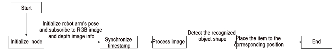
Based on the diagram above, the program’s logical flow primarily involves obtaining RGB and depth images from the camera, synchronizing their timestamps, processing the acquired images, determining object shapes based on detected contour corners, calculating object coordinates from the corresponding positions, and finally, utilizing trajectory planning for object grasping and placement.
Import Feature Pack
Import the required modules using the import statements:
cv2 for image processing with OpenCV.
rospy for ROS communication.
numpy for array operations.
message_filters for implementing message filtering and synchronization, essential for handling sensor data and messages in ROS.
Import Image message type from sensor_msgs.msg and rename it as RosImage.
Import SetBool service message type from the std_srvs.srv module.
Import the fps feature module from the vision_utils module for frame rate calculation.
Use queue for queue-related operations in multithreading.
Import the ROS message type named MultiRawIdPosDur from hiwonder_interfaces.msg for defining custom ROS messages, facilitating data transmission and communication within the ROS system.
Import modules from vision_utils for coordinate system transformation calculations.
Import pid, bus_servo_control, sdk_client, and tone modules from jetarm_sdk.
Import the library for kinematic control from jetarm_kinematics.
Import action_group_controller for action group control.
{lineno-start=}
import cv2
import rospy
import numpy as np
import message_filters
from sensor_msgs.msg import Image as RosImage
from sensor_msgs.msg import CameraInfo
from std_srvs.srv import SetBool
from vision_utils import fps
import threading
import queue
from hiwonder_interfaces.msg import MultiRawIdPosDur
from vision_utils import xyz_quat_to_mat, xyz_euler_to_mat, mat_to_xyz_euler
from jetarm_sdk import pid, bus_servo_control, sdk_client, tone
from jetarm_sdk.servo_controller import controller as actiongroup
from jetarm_kinematics import kinematics_control
Initiate RgbDepthImageNode Class (RGB Depth Image Class)
Print relevant prompt messages to the terminal. Initiate the RgbDepthImageNode class and within a loop, call the node.image_proc() method until either Ctrl+C is pressed or the ROS node is closed. Output log information indicating the shutdown (shutdown2).
279 280 281 282 283 284 285 286 287 288 289 290 291 292 293 294 295 296 | if __name__ == "__main__": print(''' ********************************************* * * * 此程序需要订阅深度摄像头节点,开启前请确保 * * 已开启摄像头节点, 通过rostopic list可查看 * * 是否有rgbd_cam 相关节点,成功运行可看到终端 * * running ... * * * ********************************************* ''') try: node = RgbDepthImageNode() while not rospy.is_shutdown(): node.image_proc() except KeyboardInterrupt: rospy.loginfo("shutdown2") |
Initialization Function of RgbDepthImageNode Class
Initialize shape_recognition node and related variable.
38 39 40 41 42 43 44 45 46 47 48 | class RgbDepthImageNode: def __init__(self): rospy.init_node('shape_recognition', anonymous=True) self.fps = fps.FPS() self.last_shape = "none" self.moving = False self.count = 0 self.endpoint = None self.sdk = sdk_client.JetArmSDKClient() config = rospy.get_param(CONFIG_NAME) self.hand2cam_tf_matrix = config['hand2cam_tf_matrix'] |
Create Servo Publisher
The servos_pub creates a servo publisher, sending messages to the /controllers/multi_id_pos_dur topic. Here, MultiRawIdPosDur is the message type used to control the positions and durations of multiple servos.
The set_servos function from the bus_servo_control module is utilized to set the initial position and duration of the servos. The parameters include the publisher instance, servo runtime (in milliseconds), and a tuple containing the IDs and rotation angles (ranging from 1-1000) of multiple servos.
50 51 52 53 54 | self.servos_pub = rospy.Publisher('/controllers/multi_id_pos_dur', MultiRawIdPosDur, queue_size=1) rospy.sleep(3) rospy.wait_for_service('/kinematics/set_joint_value_target') self.goto_default() rospy.sleep(2) |
Wait /rgbd_cam/set_ldp Service to Initiate
Established a service proxy and utilized the SetBool message type to specify the service’s request and response formats. Sent False as the argument to the /rgbd_cam/set_ldp service.
55 56 | rospy.wait_for_service('/rgbd_cam/set_ldp') rospy.ServiceProxy('/rgbd_cam/set_ldp', SetBool)(False) |
Receive Image Info
(1) Create rgb_sub image subscriber, and use message_filters.Subscriber to create a message subscriber.
The first parameter /rgbd_cam/color/image_raw represents the image topic name.
The second parameter RosImage refers to the message type.
The third parameter queue_size=1 specify the size of message queue.
(2) Create depth_sub image subscriber, and use message_filters.Subscriber to create a message subscriber.
The first parameter, /rgbd_cam/depth/image_raw, denotes the topic name for the image.
The second parameter specifies the message type as RosImage.
The third parameter, queue_size=1, specifies the size of the message queue.
(3) Create info_sub image subscriber, and use message_filters.Subscriber to create an image subscriber.
The first parameter /rgbd_cam/depth/camera_info represents the image topic name.
The second parameter CameraInfo is the message type.
The third parameter queue_size=1 specifies the size of the message queue.
58 59 60 | rgb_sub = message_filters.Subscriber('/rgbd_cam/color/image_raw', RosImage, queue_size=1) depth_sub = message_filters.Subscriber('/rgbd_cam/depth/image_raw', RosImage, queue_size=1) info_sub = message_filters.Subscriber('/rgbd_cam/depth/camera_info', CameraInfo, queue_size=1) |
Synchronize Timestamp
Establish a time synchronizer to synchronize messages from the rgb_sub and depth_sub topics. The 3 signifies a maximum buffer size of 3 messages, and 0.03 implies that messages with a timestamp difference of no more than 0.03 seconds will be considered synchronized.
62 63 64 | # 同步时间戳, 时间允许有误差在0.03s(synchronize timestamps, allowing for a time error of up to 0.03 seconds) sync = message_filters.ApproximateTimeSynchronizer([rgb_sub, depth_sub, info_sub], 3, 0.03) sync.registerCallback(self.multi_callback) #执行反馈函数(execute feedback function) |
move Function
75 76 77 78 79 80 81 82 83 84 85 86 87 88 89 90 91 92 93 94 95 96 97 98 99 100 101 102 103 104 105 106 107 108 109 110 111 112 | def move(self, shape, pose_t, angle): self.sdk.set_buzzer(int(tone.G4), 200, 100, 1) rospy.sleep(0.5) pose_t[2] += 0.02 ret1 = kinematics_control.set_pose_target(pose_t, 85) if len(ret1[1]) > 0: bus_servo_control.set_servos(self.servos_pub, 1500, ((1, ret1[1][0]), (2, ret1[1][1]), (3, ret1[1][2]), (4, ret1[1][3]),(5, ret1[1][4]))) rospy.sleep(1.5) pose_t[2] -= 0.05 ret2 = kinematics_control.set_pose_target(pose_t, 85) if angle != 0: angle = angle % 180 angle = angle - 180 if angle > 90 else (angle + 180 if angle < -90 else angle) angle = 500 + int(1000 * (angle + ret2[3][-1]) / 240) else: angle = 500 if len(ret2[1]) > 0: bus_servo_control.set_servos(self.servos_pub, 500, ((5, angle),)) rospy.sleep(0.5) bus_servo_control.set_servos(self.servos_pub, 1000, ((1, ret2[1][0]), (2, ret2[1][1]), (3, ret2[1][2]), (4, ret2[1][3]),(5, angle))) rospy.sleep(1) bus_servo_control.set_servos(self.servos_pub, 600, ((10, 550),)) rospy.sleep(0.6) if len(ret1[1]) > 0: bus_servo_control.set_servos(self.servos_pub, 1000, ((1, ret1[1][0]), (2, ret1[1][1]), (3, ret1[1][2]), (4, ret1[1][3]),(5, angle))) rospy.sleep(1) bus_servo_control.set_servos(self.servos_pub, 1000, ((1, 500), (2, 540), (3, 220), (4, 50), (5, 500), (10, 550))) rospy.sleep(1) print("shape: ", shape) if shape == "sphere": actiongroup.runAction("target_1") if shape == "cylinder": actiongroup.runAction("target_2") if shape == "cuboid": actiongroup.runAction("target_3") self.goto_default() rospy.sleep(2) self.moving = False |
Invoke the buzzer with parameters such as tone, duration (in milliseconds), volume, and 1 to enable the buzzer.
76 | self.sdk.set_buzzer(int(tone.G4), 200, 100, 1) |
Determine the shape of the recognized object, namely sphere, cylinder, and square, corresponding to three action groups: target_1, target_2, and target_3. Place the object in the respective position.
104 105 106 107 108 109 | if shape == "sphere": actiongroup.runAction("target_1") if shape == "cylinder": actiongroup.runAction("target_2") if shape == "cuboid": actiongroup.runAction("target_3") |
After placing the object, control the robotic arm to return to its initial state.
101 102 | bus_servo_control.set_servos(self.servos_pub, 1000, ((1, 500), (2, 540), (3, 220), (4, 50), (5, 500), (10, 550))) rospy.sleep(1) |
multi_callback Function
The multi_callback function receives messages for ros_rgb_image, ros_depth_image, and camera_info. It checks if self.queue is empty. If the queue is empty, it puts a tuple containing synchronized messages for ros_rgb_image, ros_depth_image, and camera_info into the queue. This tuple signifies that the three images have been successfully synchronized.
114 115 116 | def multi_callback(self, ros_rgb_image, ros_depth_image, depth_camera_info): if self.queue.empty(): self.queue.put_nowait((ros_rgb_image, ros_depth_image, depth_camera_info)) |
image_proc Function
Retrieve synchronized RGB and depth images from the queue self.queue.
119 120 | def image_proc(self): ros_rgb_image, ros_depth_image, depth_camera_info = self.queue.get(block=True) |
Create a NumPy array rgb_image to store RGB image data. Extract data from ros_rgb_image and construct the array based on image height, width, and data type.
Create a NumPy array depth_image to store depth image data. Extract data from ros_depth_image and construct the array based on image height and width.
Obtain camera intrinsics along with the height and width of the depth image.
121 122 123 | try: rgb_image = np.ndarray(shape=(ros_rgb_image.height, ros_rgb_image.width, 3), dtype=np.uint8, buffer=ros_rgb_image.data) depth_image = np.ndarray(shape=(ros_depth_image.height, ros_depth_image.width), dtype=np.uint16, buffer=ros_depth_image.data) |
Acquire the Coordinate of the Smallest Pixel Point
Copy the data from the depth image and reshape it into a one-dimensional array. Set pixel values less than or equal to 0 to 55555 to eliminate invalid depth values.
Calculate the row coordinate min_y of the pixel with the minimum depth value by performing integer division using the min_index divided by the image width (w). Integer division truncates the decimal part, yielding an integer representing the row position of the pixel with the minimum depth value in the depth image.
Multiply min_y by w (image width) and subtract the result from min_index. This yields the column coordinate min_x of the pixel with the minimum depth value.
133 134 135 136 137 | depth = np.copy(depth_image).reshape((-1, )) depth[depth<=0] = 55555 # 距离为0可能是进入死区,或者颜色问题识别不到,将距离赋一个大值(a distance of 0 could indicate an area of no return or a color recognition issue; assign a large value to distance) min_index = np.argmin(depth) # 距离最小的像素(the pixel with the minimum distance) min_y = min_index // iw min_x = min_index - min_y * iw |
Process Image
Assign the values of target_point to min_x and min_y.
Use np.clip to constrain the values in the depth image between 0 and 2000, with values exceeding this range truncated.
Convert the data type of the depth image to np.float64. Normalize the depth values to the range of 0 to 255 for subsequent visualization.
Set pixel values in the depth image greater than min_dist + 10 to 0.
Normalize and transform the updated depth image back to the range of 0 to 255.
139 140 141 142 143 | min_dist = depth_image[min_y, min_x] # 获取最小距离值(get the minimum distance measurement) sim_depth_image = np.clip(depth_image, 0, 300).astype(np.float64) / 300 * 255 depth_image = np.where(depth_image > min_dist + 15, 0, depth_image) # 将深度值大于最小距离15mm的像素置0(set the pixels with depth values greater than the minimum distance of 15mm to 0) sim_depth_image_sort = np.clip(depth_image, 0, 2000).astype(np.float64) / 2000 * 255 # depth_gray = sim_depth_image_sort.astype(np.uint8) |
Convert the depth image into a binary image where pixels with depth values less than 1 are set to 0, and the rest are set to 255.
Perform erosion on the binary image, which helps eliminate small noise or connect small holes in the image.
Apply dilation to the eroded image to restore the original shape of the objects.
Visualize the depth image as a colored image using JET colormap.
144 145 146 147 148 | depth_gray = cv2.GaussianBlur(depth_gray, (3, 3), 0) _, depth_bit = cv2.threshold(depth_gray, 1, 255, cv2.THRESH_BINARY) #depth_bit = cv2.erode(depth_bit, np.ones((3, 3), np.uint8)) #depth_bit = cv2.dilate(depth_bit, np.ones((3, 3), np.uint8)) depth_color_map = cv2.applyColorMap(sim_depth_image.astype(np.uint8), cv2.COLORMAP_JET) |
Utilize cv2.findContours to locate contours in the binary image depth_bit.
Set cv2.RETR_EXTERNAL as the contour retrieval mode, which exclusively retrieves external contours.
Choose cv2.CHAIN_APPROX_NONE as the contour approximation method.
Initialize the variable shape with the string value none.
150 151 | contours, hierarchy = cv2.findContours(depth_bit, cv2.RETR_EXTERNAL, cv2.CHAIN_APPROX_NONE) shape = 'none' |
Iterate through each contour in the list of found contours.
Calculate the area of the current contour and store the result in the variable area.
If the area of the current contour is less than 2000 (or self.moving is true), skip the current contour and proceed to the next one.
Draw the contour lines, representing the current contour (obj), in yellow on the depth_color_map image.
Compute the perimeter of the current contour and store the result in the variable perimeter.
Use cv2.approxPolyDP to approximate the contour with a polygon, reducing the number of corners. The coordinates of the vertices of the approximated polygon are stored in the variable approx.
Draw the lines of the polygon approximation, representing it in blue on the depth_color_map image.
Calculate the number of vertices in the polygon approximation and store the result in the variable CornerNum.
Compute the minimum bounding rectangle around the polygon approximation and return its top-left coordinates (x, y), width w, and height h.
153 154 155 156 157 158 159 160 161 162 163 164 165 | for obj in contours: if min_dist > 225: break area = cv2.contourArea(obj) if area < 2000 or self.moving is True: continue cv2.drawContours(depth_color_map, obj, -1, (255, 255, 0), 4) # 绘制轮廓线(draw contour line) perimeter = cv2.arcLength(obj, True) # 计算轮廓周长(calculate contour perimeter) approx = cv2.approxPolyDP(obj, 0.035 * perimeter, True) # 获取轮廓角点坐标(get contour angular point coordinates) cv2.drawContours(depth_color_map, approx, -1, (255, 0, 0), 4) # 绘制轮廓线(draw contour line) CornerNum = len(approx) x, y, w, h = cv2.boundingRect(approx) |
Determine the shape type based on the detected standard deviation of depth values and the number of corners. When the standard deviation is greater than 1, it is considered a circular shape or a more complex figure. In this case, if the number of corners is greater than 4, it is recognized as a sphere; otherwise, if it is less than or equal to 4, it is considered a cylinder.
If the standard deviation is less than or equal to 1, it indicates that the shape may not be very complex, possibly a cylindrical pattern or a planar pattern. In this scenario, if the number of corners is equal to 4, it is identified as a rectangular prism; otherwise, it is considered a cylinder.
178 179 180 181 182 183 184 185 186 187 188 189 190 191 192 193 194 195 | if depth_std > 1: if CornerNum > 4: objType = "sphere_1" # 球体(sphere) elif CornerNum == 4: objType = "cylinder_1" # 圆柱体(cylinder) else: objType = "none" else: if CornerNum == 4: if min_y > (y + int(h / 10 * 7)): objType="cuboid_1" # 立方体/长方体(cube/cuboid) else: objType="cylinder_2" # 圆柱体(cylinder) else: if 4 < CornerNum < 10: objType="cylinder_2" # 圆柱体(cylinder) else: objType = "none" |
Check if the current shape in the current frame is the same as the shape in the previous frame and not equal to none. If true, print the current counter value (self.count) and increment the counter by 1.
If the shape has changed but is not none, reset the counter value.
226 227 228 229 230 | if self.last_shape == shape and shape != 'none': #print(self.count) self.count += 1 else: self.count = 0 |
Estimate Pose and Execute Corresponding Action
Examine contour information. If contour is not
None, calculate the minimum enclosing circle of the object contour and retrieve the center point, camera intrinsics for that target.
231 232 233 | if contour is not None : (cx, cy), r = cv2.minEnclosingCircle(obj) K = depth_camera_info.K |
Convert pixel coordinates and depth values into coordinates in the camera coordinate system. Transform the information within the position function into a pose matrix and make slight adjustments.
234 235 | position = depth_pixel_to_camera((cx, cy), min_dist / 1000, (K[0], K[4], K[2], K[5])) position[0] -= 0.01 |
Subsequently, convert the parameters from the camera coordinate system to the world coordinate system. If the conditions are met, initiate a new thread, invoke the self.move function to grasp objects of a specific shape, and finally update the information for the current shape.
236 237 238 239 240 241 242 243 244 245 246 247 248 249 250 251 252 253 254 255 256 257 258 259 260 261 | pose_end = np.matmul(self.hand2cam_tf_matrix, xyz_euler_to_mat(position, (0, 0, 0))) world_pose = np.matmul(self.endpoint, pose_end) pose_t, pose_r = mat_to_xyz_euler(world_pose) print(pose_t[2]) min_x, min_y = cx, cy print(pose_t) angle = 0 offset_x = 0.008 offset_y = 0 offset_z = 0.00 pose_t[0] += offset_x pose_t[1] += offset_y pose_t[2] += offset_z if shape == "cylinder_1" or shape == "cuboid_1": center, (width, height), angle = cv2.minAreaRect(contour) if angle < -45: angle += 90 if width > height and width / height > 1.5: print("wh: ", width, height) angle = angle + 90 cv2.drawContours(depth_color_map, [np.int0(cv2.boxPoints((center, (width,height), angle)))], -1, (0, 0, 255), 2, cv2.LINE_AA) if self.count > 5: self.count = 0 self.moving = True threading.Thread(target=self.move, args=(shape[:-2], pose_t, angle)).start() self.last_shape = shape |
Marking Corresponding Depth Values on Pseudocolored and BGR Images
Displaying depth values as text on pseudocolored and BGR images involves drawing larger black text and slightly offset smaller gray text. The parameters correspond to the processed image, text content, starting position, font, size, color, line width, and an anti-aliasing line drawing mode for smoother lines.
222 223 224 | cv2.rectangle(depth_color_map, (x, y), (x + w, y + h), (255, 255, 255), 2) cv2.putText(depth_color_map, objType[:-2], (x + w // 2, y + (h //2) - 10), cv2.FONT_HERSHEY_COMPLEX, 1.0, (0, 0, 0), 2, cv2.LINE_AA) cv2.putText(depth_color_map, objType[:-2], (x + w // 2, y + (h //2) - 10), cv2.FONT_HERSHEY_COMPLEX, 1.0, (255, 255, 255), 1) |
Update image frame rate.
266 | self.fps.update() |
Concatenate the RGB image and pseudocolored depth image horizontally to create a single image. Then, use cv2.imshow to display the final image on the depth window.
268 269 | result_image = np.concatenate([depth_color_map, bgr_image], axis=1) cv2.imshow("depth", result_image) |
Check for keyboard input, and if any key is pressed, close the node.
271 272 273 | key = cv2.waitKey(1) if key != -1: rospy.signal_shutdown('shutdown1') |
In the event of an exception in the code, capture the exception and log the error information as a ROS error message.
275 276 | except Exception as e: rospy.logerr('callback error:', str(e)) |