7. Secondary Development Course
7.1 Sensor Installation and Wiring Instruction
Secondary Development Library File Introduction
During development process, library files can be used for ease of program invocation. These will include official Arduino libraries such as “Servo” and “tone”, as well as our custom libraries like “Ultrasound”, “SparkFun_APDS9960” and “FastLED”.
This section will explain the custom library files and the main programs used for secondary development of the miniArm robotic arm. The FastLED library has been packaged. There will not be further analyzed in this document.
7.2 Ultrasonic Library File (Ultrasound)
“Ultrasound” is a library function that controls the luminous ultrasonic module to send and read information, set the color of RGB lights on the module, and get the measured distance. In the subsequent program involving ultrasonic ranging and ultrasonic grasping, this function needs to be called to detect distance and control the color change of module lights.
Here are some functions that used frequently.
7.2.1 Member Function (Ultrasound::Color)
80 81 82 83 84 85 86 87 88 89 | void Ultrasound::Color(uint8_t r1, uint8_t g1, uint8_t b1, uint8_t r2, uint8_t g2, uint8_t b2) { uint8_t RGB[6]; uint8_t value = RGB_WORK_SIMPLE_MODE; wireWriteDataArray(ULTRASOUND_I2C_ADDR, RGB_WORK_MODE,&value,1); RGB[0] = r1;RGB[1] = g1;RGB[2] = b1;//RGB1 RGB[3] = r2;RGB[4] = g2;RGB[5] = b2;//RGB2 wireWriteDataArray(ULTRASOUND_I2C_ADDR, RGB1_R,RGB,6); } |
This is one of the member functions of the Ultrasound class, primarily used for controlling the color of the RGB light on the ultrasonic module. It receives six parameters, namely r1, g1, b1, and r2, b2, g2, respectively representing the red, green and blue colors of the left and right RGB lights on the luminous module.
| Ultrasound::Color() | |||
| Description | Control the RGB light color of luminous ultrasonic | ||
| Parameter List | r1、g1、b1、r2、g2、b2 | Return Value | none |
| Usage Instruction |
(1) Ultrasound ul; (create luminous ultrasonic object) (2) ul.Color(0,0,255,0,0,255); |
||
Then, the values of the two colors passed in earlier, RGB1 and RGB2, are assigned respectively to the first six elements. Finally, use the wireWriteDataArray function to send the RGB value of two colors set before to ultrasonic sensor through I2C protocol.
7.2.2 Member Function (Ultrasound::GetDistance)
This is one of the member functions of the Ultrasound class. It is used for getting distance from luminous ultrasonic module.
The code uses wireReadDataArray function to read data from I2C address of the ultrasonic sensor. Starting from the offset 0 of the address ULTRASOUND_I2C_ADDR, read 2 bytes of data and store it in the variable “distance”. That is getting the distance data of ultrasonic module.
92 93 94 95 96 97 | u16 Ultrasound::GetDistance() { u16 distance; wireReadDataArray(ULTRASOUND_I2C_ADDR, 0,(uint8_t *)&distance,2); return distance; } |
| Ultrasound::GetDistance() | |||
| Description | Get measured distance of luminous ultrasonic module directly | ||
| Parameter List | none | Return Value | Return the distance measurement of the u16 class |
| Usage Instruction |
(1) Ultrasound ul; (create luminous ultrasonic object) (2) ul.GetDistance(); (return the directly measured distance value, which may have interference) |
||
7.2.3 Member Function (Ultrasound::Filter)
Filter is one of the member functions of the Ultrasound class. It is used for filtering the data obtained in the GetDistance function and reducing interference to obtain a more soother average value.
Firstly, the program defines a filter size of 3, which is used for storing three ultrasonic distance measurements read recently. Then the program declares a static integer array filter_buf with a size of FILTER_N + 1 (i.e., 4).
Read a new measurement from the GetDistance function, and store it in the last position of the filter_buf array. When a certain amount of data is accumulated, move all the data in the “filter_buf” array one byte to the left. That means discard the least significant data. And then accumulate all the data into the variable filter_sum, facilitating the calculation of the total sum of all stored data.
Finally, return the function to calculate the obtained average value. This average value is calculated by dividing the accumulated sum by the length of the filter, and the result is forced to be converted to an integer type and returned.
100 101 102 103 104 105 106 107 108 109 110 111 112 | #define FILTER_N 3 //递推平均滤波法(recursive averaging filter)
static int filter_buf[FILTER_N + 1];
int Ultrasound::Filter(void) {
int i;
int filter_sum = 0;
filter_buf[FILTER_N] = GetDistance(); //读取超声波测值(read ultrasonic detection value)
for(i = 0; i < FILTER_N; i++) {
filter_buf[i] = filter_buf[i + 1]; // 所有数据左移,低位仍掉(shift all data to the left and remove the low bits)
filter_sum += filter_buf[i];
}
return (int)(filter_sum / FILTER_N);
}
|
| Ultrasound::Filter() | |||
| Description | Get the filtered measurement | ||
| Parameter List | none | Return Value | Return the filtered distance measurement of the int class |
| Usage Instruction |
(1) Ultrasound ul; (create luminous ultrasonic object) (2) ul.Filter(); (return the filtered value, which may remove interference) |
||
7.3 Ultrasonic Ranging
In this section, you will learn how to use the glowing ultrasonic module to test the obstacle distance, achieve the function of opening and closing the mechanical claw and control the color change of RGB lights.
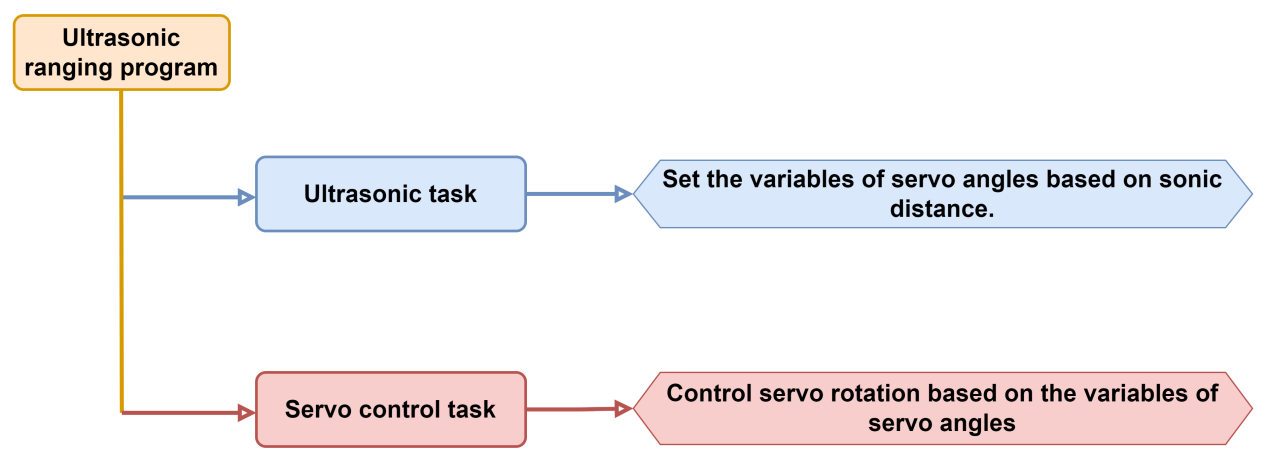
7.3.1 Program Flowchart
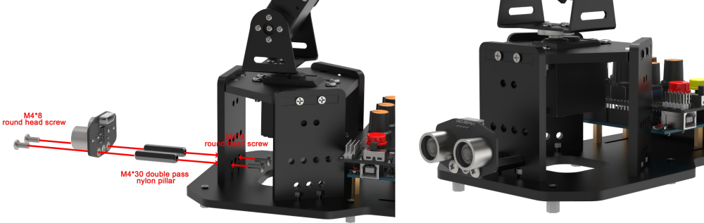
7.3.2 Ultrasonic Sensor

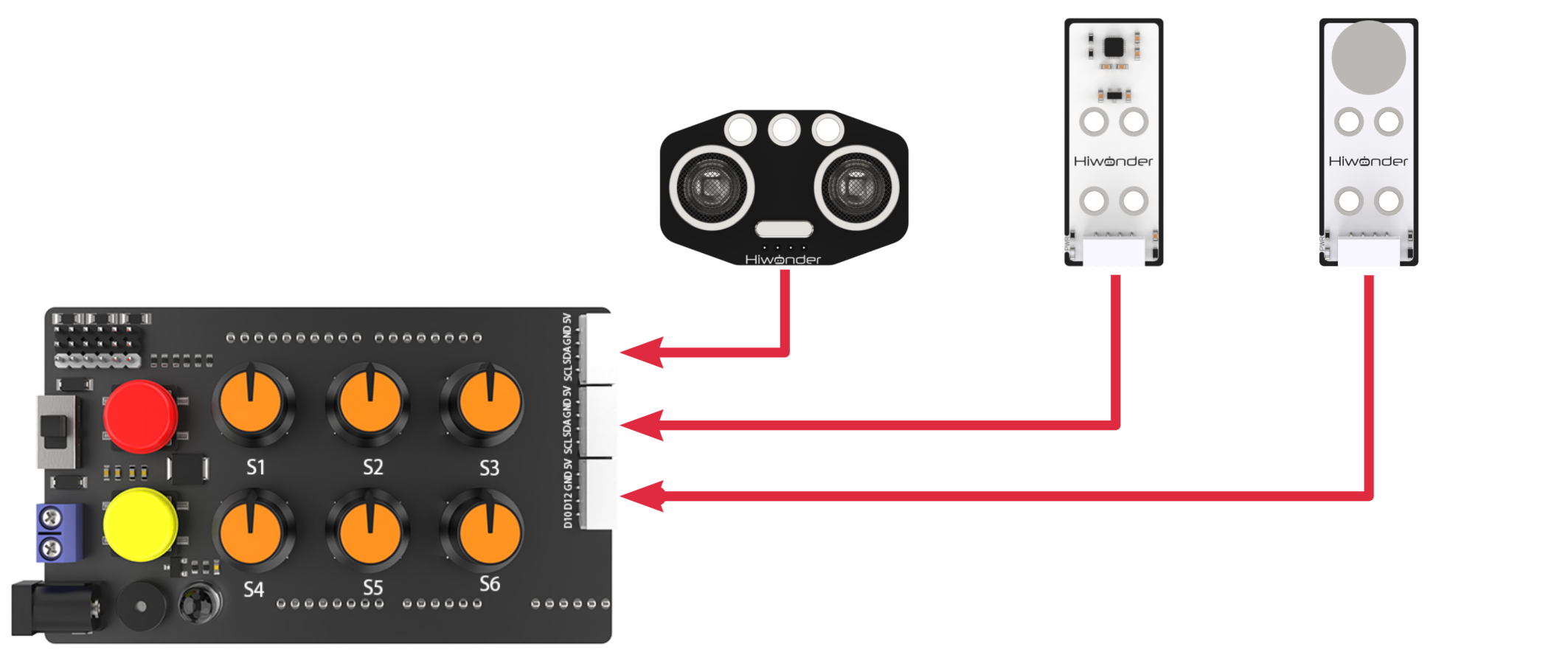
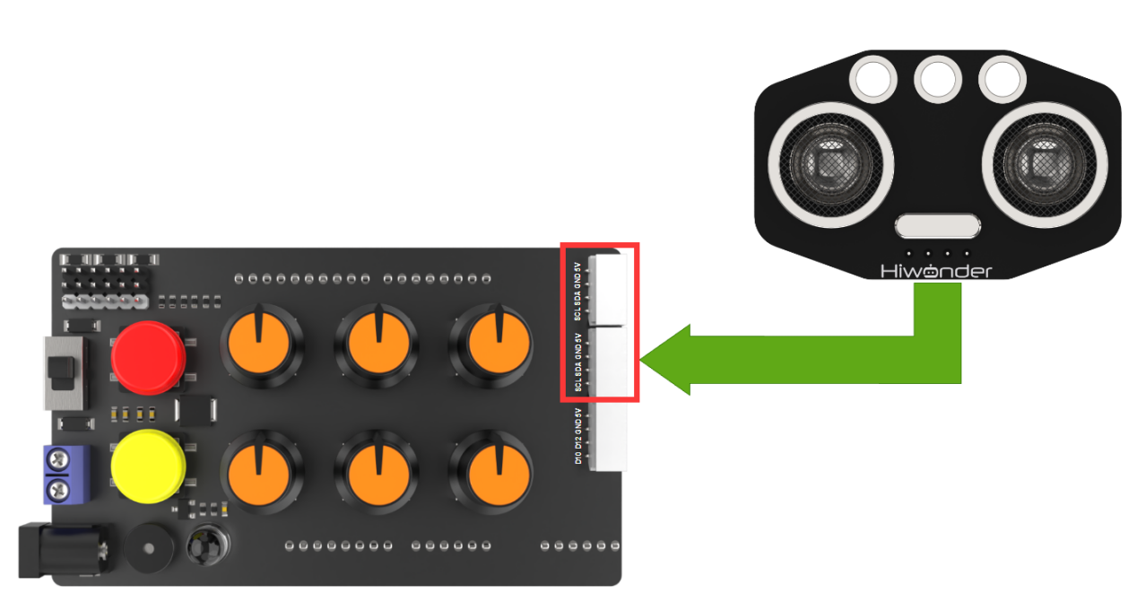
This is a glowing ultrasonic ranging module. The module adopts I2C communication interface, which can read distance measured by ultrasonic sensor through I2C communication.
Sensor Wiring
Connect the ultrasonic module to any I2C interface through 4Pin cable.
7.3.3 Program Download
Note
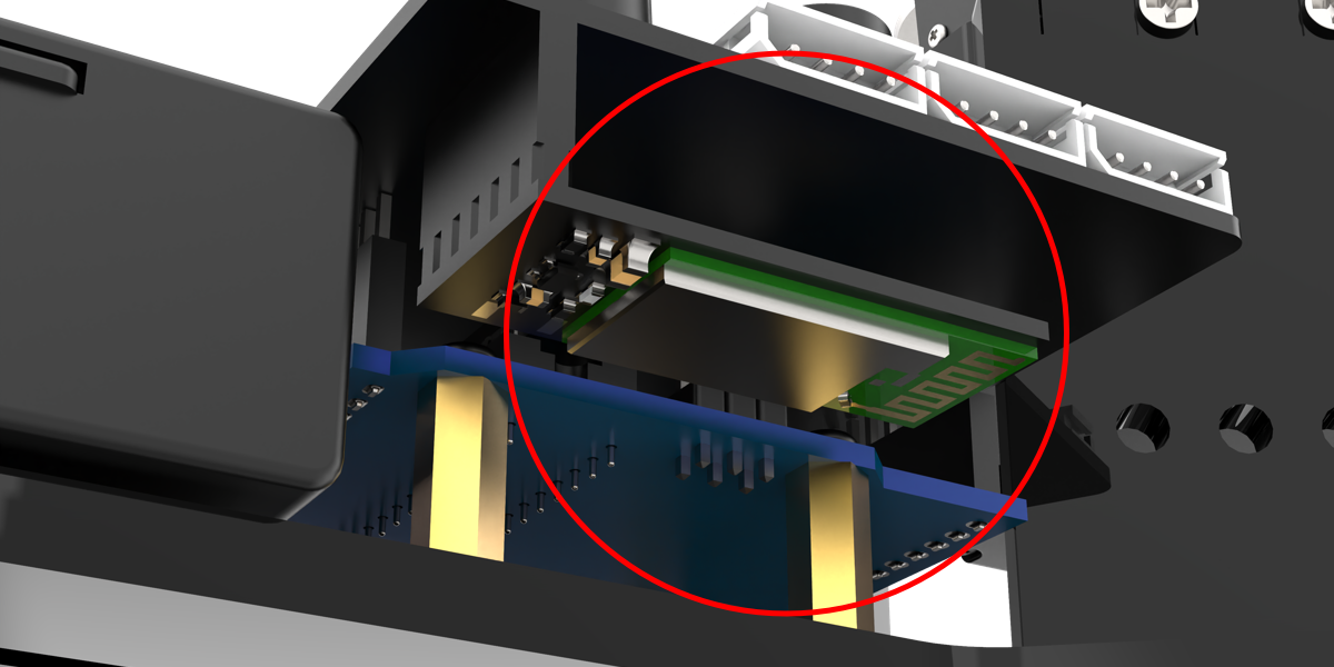
Remove the Bluetooth module before downloading the program, otherwise the serial port conflict will lead to program download failure.
Please turn the switch of the battery box to “OFF” when connect Type-B download cable to avoid the cable touch the power pins of expansion board by mistake, which may cause a short circuit.
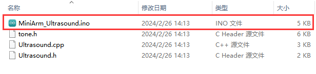
(1) Locate “MiniArm_Ultrasound\MiniArm_Ultrasound.ino” program file in the same path as this document.
(2) Connect Arduino to the computer through UNO Type-B cable.

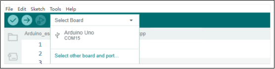
(3) Click “Select Development Board” option. The software will automatically test current Arduino serial port, then click to connect.
(4) Click  to download the program to Arduino, then wait for download to complete.


7.3.4 Program Outcome
After powering on, the robotic arm will return to the initial position. Meanwhile, the RGB lights on the expansion board and glowing ultrasonic module will emit blue.
Place the obstacle directly in front of the ultrasonic module and slowly move it closer.
When the distance is greater than 20cm, the mechanical claw will open and the RGB lights on the ultrasonic module and expansion board will emit blue.
When the distance is less than 10cm and greater than 20cm, the obstacle will close to the robotic arm and the mechanical claw will close slowly. Meanwhile, the color of RGB lights on the ultrasonic module and the expansion board will change from blue to purple.
When the distance is less than 10cm, the mechanical claw will close. And the RGB lights on the ultrasonic module and the expansion board will emit red.
7.3.5 Program Brief Analysis
Import Library File
6 7 8 9 10 | #include <FastLED.h> //import LED library #include <Servo.h> //import servo library #include "tone.h" //tone library #include "Ultrasound.h" //import ultrasonic library #include <EEPROM.h> |
Import the library files required for this program, including the RGB control library, servo control library, buzzer library and ultrasonic control library.
Define Pins and Create Objects
(1) The EEPROM start flag, the start and data addresses of the servo deviation data, and the length of the servo deviation data are defined.
12 13 14 15 | #define EEPROM_START_FLAG "HIWONDER" #define EEPROM_SERVO_OFFSET_START_ADDR 0u #define EEPROM_SERVO_OFFSET_DATA_ADDR 16u #define EEPROM_SERVO_OFFSET_LEN 6u |
(2) Define the tones of the two buzzers and the Arduino pins connected to the hardware: mainly consist of six servo pins, one buzzer pin and one RGB light pin.
17 18 19 20 21 22 23 | const static uint16_t DOC5[] = { TONE_C5 }; const static uint16_t DOC6[] = { TONE_C6 }; /* pins definition */ const static uint8_t servoPins[6] = { 7, 6, 5, 4, 3, 2 }; const static uint8_t buzzerPin = 11; const static uint8_t rgbPin = 13; |
(3) Create the objects of the RGB light, servo and ultrasonic sensor. Meanwhile, variables controlled by the servo are created. For example, the extended_func_angles array is used for storing desired angle for each servo, and the servo_angles array is used for storing the actual angle of servo with range from 0 to 180. In addition, angle limits are set for each joint of the robotic arm.
27 28 29 30 31 32 33 34 35 36 37 38 39 40 | //servo control object Servo servos[6]; //create ultrasonic object Ultrasound ul; /* Angle values used in secondary development routines */ static uint8_t extended_func_angles[6] = { 73,10,161,57,90,90 }; /* Limitations on joint angles */ const uint8_t limt_angles[6][2] = {{0,82},{0,180},{0,180},{0,180},{0,180},{0,180}}; /* The angle value of the actual control of the servo */ static uint8_t servo_angles[6] = { 73,10,161,57,90,90 }; static int8_t servo_offset[5]; static uint8_t servo_expect[5]; static uint8_t eeprom_read_buf[16]; |
For the desired value and the actual value, you can see the servo_control function called in the loop main function.
If you want the servo to approach to the target position gradually, call this line of code servo_angles[i] = servo_angles[i] * 0.9 + extended_func_angles[i] * 0.1 in the control task function.
This causes the servo to move each time by adding a portion of the servo pulse-width of the desired value to its previous position. After each movement, the current new data will be reassigned. This enables the robotic arm to stop moving when the target position is reached.
149 150 151 152 153 154 155 156 157 158 159 160 161 | for (int i = 0; i < 5; ++i) { servo_expect[i] = extended_func_angles[i] + servo_offset[i]; if(servo_angles[i] > servo_expect[i]) { servo_angles[i] = servo_angles[i] * 0.9 + servo_expect[i] * 0.1; if(servo_angles[i] < servo_expect[i]) servo_angles[i] = servo_expect[i]; }else if(servo_angles[i] < servo_expect[i]) { servo_angles[i] = servo_angles[i] * 0.9 + (servo_expect[i] * 0.1 + 1); if(servo_angles[i] > servo_expect[i]) servo_angles[i] = servo_expect[i]; } |
(4) Define servo-related variables and EEPROM read buffer.
38 39 40 | static int8_t servo_offset[5]; static uint8_t servo_expect[5]; static uint8_t eeprom_read_buf[16]; |
servo_offset denotes the servo’s deviation, while servo_expect represents the expected value of the servo accounting for this deviation.
(5) Define the variable used for controlling buzzer, and declare the task function to execute different control task.
47 48 49 50 51 | //servo control static void servo_control(void); //ultrasonic task static void ultrasound_task(void); static void read_offset(void); |
tune_num variable means the tone notation; tune_beat variable means rhythm; servo_control function is used for controlling servo; ultrasound_task function is used for reading ultrasonic sensor data.
Initialization Settings
(1) The setup() function is used for initializing the relevant hardware devices. First is the serial port, set the baud rate for communication to 115200 and the read data timeout to 500ms.
53 54 55 56 57 | void setup() { // put your setup code here, to run once: Serial.begin(115200); // set the read data timeout of serial port Serial.setTimeout(500); |
(2) Assign the servo IO port, use the FastLED library to initialize the RGB light on the expansion board and connect it to the RGB pin. Set the RGB color to green through rgbs[0] = CRGB(0, 255, 0). Finally, use the FastLED.show function to display the set color.
60 61 62 63 64 65 66 67 | for (int i = 0; i < 6; ++i) { servos[i].attach(servoPins[i],500,2500); } //initialize the RGB light and control it FastLED.addLeds<WS2812, rgbPin, GRB>(rgbs, 1); rgbs[0] = CRGB(0, 0, 100); FastLED.show(); |
(3) Set the buzzer interface to output mode and call the tone() function to make the buzzer sound. Call noTone() function to stop sounding the buzzer after a delay of 100ms.
69 70 71 72 73 | //initialize buzzer and beep one time pinMode(buzzerPin, OUTPUT); tone(buzzerPin, 1000); delay(100); noTone(buzzerPin); |
Read Deviation Angle
75 76 | read_offset(); //read deviation angle |
(1) Firstly, get the start flag of the deviation value in memorizer and store it in the eeprom_read_buf read buffer.
58 59 60 | for (int i = 0; i < 6; ++i) { servos[i].attach(servoPins[i],500,2500); } |
(2) Determine whether the start flag bit in the memorizer is correct. If it is correct, the eeprom_read_buf buffer will be cleared. The serial port prints the read offset string, and then starts to get the deviation value.
168 169 170 171 172 173 174 | if (strcmp(eeprom_read_buf, EEPROM_START_FLAG) == 0) { memset(eeprom_read_buf, 0 , sizeof(eeprom_read_buf)); Serial.println("read offset"); for (int i = 0; i < 5; ++i) { eeprom_read_buf[i] = EEPROM.read(EEPROM_SERVO_OFFSET_DATA_ADDR + i); } memcpy(servo_offset , eeprom_read_buf , 6); |
(3) Get 5 servo offset value in the memorizer and store it to the read buffer. Use memcpy to copy the data in the read buffer to the servo_offset variable.
Since there are positive and negative deviation values, and the eeprom_read_buf variable is an unsigned variable, we convert the deviation data from an unsigned number to a signed number by memcpy.
168 169 170 171 172 173 174 | if (strcmp(eeprom_read_buf, EEPROM_START_FLAG) == 0) { memset(eeprom_read_buf, 0 , sizeof(eeprom_read_buf)); Serial.println("read offset"); for (int i = 0; i < 5; ++i) { eeprom_read_buf[i] = EEPROM.read(EEPROM_SERVO_OFFSET_DATA_ADDR + i); } memcpy(servo_offset , eeprom_read_buf , 6); |
Ultrasonic Detection
After initialization is complete, the next step is to call the ultrasonic task function ultrasound_task within the main loop function. The function is used to implement distance measurement functionality. It first defines the variable “last_tick”, which is mainly used to calculate the time intervals.
90 91 92 93 94 95 96 97 98 99 100 101 102 | // Ultrasonic task void ultrasound_task(void) { static uint32_t last_ul_tick = 0; // delay 100ms if (millis() - last_ul_tick < 100) { return; } last_ul_tick = millis(); // Obtain ultrasonic distance int dis = ul.Filter(); // Serial.println(dis); |
Next, check if 100ms have passed since the last call to the ultrasound_task function. If it passed, the following code is executed. Otherwise, the function returns directly. The millis function is the time since the Arduino board started. In this way, the function ensures that the task of detecting the distance is performed every 100ms.
Then, get filtered ultrasonic measurements through the ul.Filter function, and store the outcome in the variable “dis”.
Execution Feedback
(1) If the detected obstacle distance is greater than 200mm, control the servo No.1~5 to rotate to the 180° to open the mechanical claw. Meanwhile, control the RGB lights on the glowing ultrasonic module and the expansion board emit blue through rgbs and ul.color function.
rgbs.r rgbs.g rgbs.b represent the brightness values of the RGB primary colors for the lights on the expansion board. Meanwhile, ul.color(0,0,255,0,0,255) represents the brightness values of the RGB primary colors for the left and right lights of the glowing ultrasonic.
104 105 106 107 108 109 110 111 112 113 114 115 | // If it is greater than 200mm if(dis >= 200) { //Open your claws extended_func_angles[0] = 0; // RGB light blue rgbs[0].r = 0; rgbs[0].g = 0; rgbs[0].b = 255; FastLED.show(); // Luminescent ultrasonic blue ul.Color(0,0,255,0,0,255); |
(2) If the distance of the obstacle is detected to be less than 50mm, then control the servo 1~5 to rotate to the 0° position. That is close the mechanical claw. Meanwhile, control the RGB lights on the glowing ultrasonic module and the expansion board to display red color through the rgbs and ul.color function.
116 117 118 119 120 121 122 123 124 125 126 | }else if(dis <= 50) //if it is less than 50mm { //close the claw extended_func_angles[0] = 82; // RGB red rgbs[0].r = 255; rgbs[0].g = 0; rgbs[0].b = 0; FastLED.show(); // glowing ultrasonic red ul.Color(255,0,0,255,0,0); |
(3) When the distance of the obstacle is between 50mm and 200mm, the R and B in the color RGB are set by the “map” function according to the change of “dis”. For example, map(dis,50,200,255,0) is to map the obstacle distance “dis” to the R element, where the range of “dis” is 50mm~200mm. The brightness range of R is 255~0.
For mapping servo angles based on obstacle distance, you can also refer to the above content. Similarly, it involves mapping obstacle distance to the range of servo angles (0~180°) for opening and closing the gripper.
127 128 129 130 131 132 133 134 135 136 137 138 | }else{ /* the color changes according to the variation. The closer it gets, the larger the R (red) and the smaller the B (blue). Conversely, the farther away, the opposite occurs */ int color[3] = {map(dis , 50 , 200 , 255 , 0),map(dis , 50 , 200 , 0 , 255),0}; // The mechanical claw closes as it gets closer and opens as it gets farther away uint8_t angles = map(dis , 50 , 200 , 82 , 0); extended_func_angles[0] = angles; rgbs[0].r = color[0]; rgbs[0].g = color[1]; rgbs[0].b = color[2]; FastLED.show(); ul.Color(color[0],color[1],color[2],color[0],color[1],color[2]); |
Servo Control Task
(1) In the servo control task, the same variable last_tick is used for delay processing.
142 143 144 145 146 147 148 | // servo control task void servo_control(void) { static uint32_t last_tick = 0; if (millis() - last_tick < 20) { return; } last_tick = millis(); |
(2) Next, get the desired value of the servo through action_ctl object. Please note that the desired value at this point is the result of the desired value plus the deviation outcome of servo. Therefore, this desired value is the actual desired value. Finally, the actual desired value of the servo is assigned to the actual control angle. Then pass it to the servo object to actually control the rotation of the servo.
148 149 150 151 152 153 154 155 156 157 158 159 160 161 162 163 164 165 | for (int i = 0; i < 5; ++i) {
servo_expect[i] = extended_func_angles[i] + servo_offset[i];
if(servo_angles[i] > servo_expect[i])
{
servo_angles[i] = servo_angles[i] * 0.9 + servo_expect[i] * 0.1;
if(servo_angles[i] < servo_expect[i])
servo_angles[i] = servo_expect[i];
}else if(servo_angles[i] < servo_expect[i])
{
servo_angles[i] = servo_angles[i] * 0.9 + (servo_expect[i] * 0.1 + 1);
if(servo_angles[i] > servo_expect[i])
servo_angles[i] = servo_expect[i];
}
servo_angles[i] = servo_angles[i] < limt_angles[i][0] ? limt_angles[i][0] : servo_angles[i];
servo_angles[i] = servo_angles[i] > limt_angles[i][1] ? limt_angles[i][1] : servo_angles[i];
servos[i].write(i == 0 || i == 5 ? 180 - servo_angles[i] : servo_angles[i]);
}
}
|
Let’s further explain the concept of ideal desired value and actual desired value here. In the action_ctl object, extended_func_angles is the ideal desired value, which excludes deviation due to servo structure. In the actual project,
servos often have a certain range of deviations due to their mechanical structure. To achieve more accurate control of the servo angle, we calculate the additional angle needed for the servo to reach the ideal position by adjusting for this deviation. This additional angle can be positive, negative, or zero. Then, during actual servo control, add this deviation value to the ideal expected angle, resulting in the actual expected angle.
7.3.6 Function Extension
Here demonstrate how to modify the color transition of RGB lights from the original gradient purple to yellow as an illustration. The specific modifications can be referred in the following steps:
(1) Locate the mapping instructions in the program that control the RGB lights to change color according to the distance. The R and B in the color RGB are set by the “map” function according to the change of “dis”. “map(dis,50,200,255,0)” is to map the obstacle distance “dis” to the R element. “map(dis,50,200,0,255)” is to map the obstacle distance “dis” to the B element.
As a result, as the distance decreased, the proportion of red color increases while the proportion of blue color decreases, displaying a gradient color that appears purple.

(2) To replace the mapped element from the B element to the G element in RGB, it’s important to note that the range of color elements is from 0 to 255. Then download the program again. In this way, as the obstacle gets closer, the proportion of red color increases while the proportion of green color decreases, resulting in the RGB lights displaying a gradient color that appears yellow.

You can visit the following link to access information about the RGB color table: https://www.bchrt.com/tools/rgbcolor/.
7.3.7 FAQ
Q: since the code was upload, the distance measured by the ultrasound is always 0.
A: please check that you have connected the 4-pin cable to the I2C interface and turn the knob on the expansion board to the initial position.
Q: the distance measured by the ultrasonic sensor is sometimes accurate, and sometimes inaccurate.
A: please use a smooth and flat object for distance measurement.
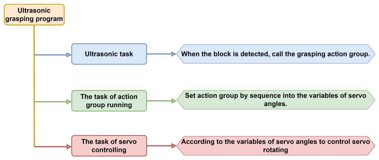
7.4 Ultrasonic Grasping
In this section, you can learn how to use a glowing ultrasonic module to detect the obstacle’s distance, and program the robotic arm to grasp and release a block, as well as control the color of the RGB light.
7.4.1 Program Flowchart
7.4.2 Ultrasonic Sensor
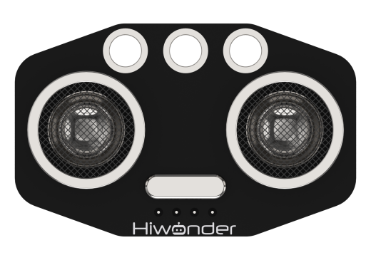
This is a glowing ultrasonic ranging module. It adopts an I2C communication interface, which can read the range measured by an ultrasonic sensor through I2C communication.
Wiring
Connect the ultrasonic module to an I2C interface on the expansion board with the 4Pin wire.

7.4.3 Program Download
Note
Remove the Bluetooth module before downloading the program. Or the program will fail to download because of the serial port conflict.
Please switch the battery box to the “OFF” when connecting the Type-B download cable. This action prevents the download cable from accidentally touching the power pins of the expansion board, which may cause a short circuit.
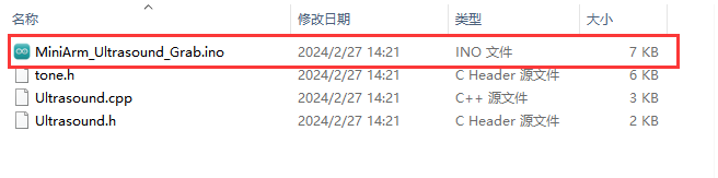
(1) Locate the “MiniArm_Ultrasound_Grab.ino” program file in “Program File/MiniArm_Ultrasound_Grab” in the same directory of this section.
(2) Connect Arduino to the computer with the UNO cable (Type-B).

(3) Click “Select Development Board”, and the software will automatically detect the current Arduino serial port. Next, click to connect.

(4) Click  to download the program into Arduino. Then just wait for it to complete.


7.4.4 Program Outcome
After powered on, the robotic arm returns to the neutral position mode first. Then it gets into the preparatory action of grasping the block, and the RGB light on the ultrasonic sensor simultaneously turns blue.
Place the block about 4cm in front of the ultrasonic sensor. The buzzer will make a short sound, then the robotic arm will grasp the block and place it on the left side (from the robotic arm’s view). During the grasping process, the RGB light on the expansion board turns red.
7.4.5 Brief Program Analysis
Import Library File
6 7 8 9 10 | #include <FastLED.h> //导入LED库(import LED library) #include <Servo.h> //导入舵机库(import servo library) #include "tone.h" //音调库(import tone library) #include "Ultrasound.h" //导入超声波库(import ultrasonic library) #include "mini_servo.h" |
Import the necessary libraries for the control of RGB, servo, and MiniArm, as well as the ultrasonic library for the game.
Pin Definition and Object Creation
(1) Initially, the tone of two buzzers and the Arduino pins for hardware connections are defined, primarily including six servo pins, one buzzer pin, and one RGB LED pin.
12 13 14 15 16 17 18 | const static uint16_t DOC5[] = { TONE_C5 }; const static uint16_t DOC6[] = { TONE_C6 }; /* 引脚定义(define pins) */ const static uint8_t servoPins[5] = { 7, 6, 5, 4, 3};//舵机引脚定义(define servo pins) const static uint8_t buzzerPin = 11; const static uint8_t rgbPin = 13; |
(2) Then, create the control objects of RGB lights, action groups, and servos. The variables of the servo control are also created. The limit_angle sets angle limits for each joint of the robotic arm. The servo_angles array is used to store the actual angles of each servo, ranging from 0 to 180.
20 21 22 23 24 25 26 27 28 29 30 | //RGB灯控制对象(RGB LED control object) static CRGB rgbs[1]; //动作组控制对象(action group control object) HW_ACTION_CTL action_ctl; //舵机控制对象(servo control object) Servo servos[5]; // 创建超声波对象(create ultrasonic object) Ultrasound ul; const uint8_t limt_angles[5][2] = {{0,82},{0,180},{0,180},{0,180},{0,180}}; /* 各个关节角度的限制(angle limit for each joint) */ static float servo_angles[5] = { 41 ,12 ,174 ,68 ,84 }; /* 舵机实际控制的角度数值(angle values for actual servo control) */ |
(3) In the control object program of the action group mini_servo.h, the construction function defines the variable extended_func_angles, which is the desired angle value of servo angles. The related functions used to control executing action groups and read deviation are also defined.
11 12 13 14 15 16 17 18 19 20 21 22 23 24 25 26 27 | class HW_ACTION_CTL{ public: /* the using angles of secondary development example */ uint8_t extended_func_angles[5] = { 41 ,12 ,174 ,68 ,84 }; //Control execution action group void action_set(int num); int action_state_get(void); void action_task(void); void read_offset(); int8_t* get_offset(void); private: //Action group control variables int action_num = 0; int8_t servo_offset[5]; uint8_t eeprom_read_buf[16]; }; |
Regarding the desired and actual values, you can check the servo_control function called in the loop main function.
If you want the servo to gradually move towards the target position, you need to call servo_angles[i] = servo_angles[i] * 0.9 + extended _func_ a ngles[i] * 0.1 in the control task function.
This allows the servo to move each time at 90% of the actual value and 10% of the expected value, so that the actual value will gradually approach the expected value. And when it is equal to the expected value, the robotic arm stops moving.
154 155 156 157 158 159 160 161 162 163 164 165 166 167 168 169 170 171 172 173 174 175 | for (int i = 0; i < 5; ++i) {
if(servo_angles[i] > action_ctl.extended_func_angles[i])
{
servo_angles[i] = servo_angles[i] * 0.9 + action_ctl.extended_func_angles[i] * 0.1;
if(servo_angles[i] < action_ctl.extended_func_angles[i])
servo_angles[i] = action_ctl.extended_func_angles[i];
}else if(servo_angles[i] < action_ctl.extended_func_angles[i])
{
servo_angles[i] = servo_angles[i] * 0.9 + (action_ctl.extended_func_angles[i] * 0.1 + 1);
if(servo_angles[i] > action_ctl.extended_func_angles[i])
servo_angles[i] = action_ctl.extended_func_angles[i];
}
servo_angles[i] = servo_angles[i] < limt_angles[i][0] ? limt_angles[i][0] : servo_angles[i];
servo_angles[i] = servo_angles[i] > limt_angles[i][1] ? limt_angles[i][1] : servo_angles[i];
servos[i].write(i == 0 || i == 5 ? 180 - servo_angles[i] : servo_angles[i]);
Serial.print(servo_angles[i]);
Serial.print(" ");
}
Serial.println();
}
|
(4) Please note that task functions execute different control tasks. The servo_control function controls the servo. The play_tune() function sets the buzzer’s sound. The tune_task function controls the buzzer. And the ultrasound_task function reads the ultrasonic sensor data.
37 38 39 40 | static void servo_control(void); //Servo control void play_tune(uint16_t *p, uint32_t beat, uint16_t len); /* Buzzer control interface */ void tune_task(void); /* Buzzer control task */ static void ultrasound_task(void); // Ultrasonic task |
Initialization Setting
(1) The setup () function mainly initializes associated hardware devices. Starting with the serial port, which sets the baud rate as 115200 and a read timeout as 500ms.
42 43 44 45 46 | void setup() { // put your setup code here, to run once: Serial.begin(115200); // 设置串行端口读取数据的超时时间(set the timeout for serial port reading data) Serial.setTimeout(500); |
(2) Assign servo IO port and use the FastLED library to initialize the RGB light on the expansion board and connect it to the rgbPin. Set the color of RGB as blue by rgbs[0] = CRGB(0, 0, 100). Next, use the FastLED.show function to display the set color.
48 49 50 51 52 53 54 55 56 | // 绑定舵机IO口(bind servo IO pin) for (int i = 0; i < 5; ++i) { servos[i].attach(servoPins[i],500,2500); } //RGB灯初始化并控制(initialize and control RGB LED) FastLED.addLeds<WS2812, rgbPin, GRB>(rgbs, 1); rgbs[0] = CRGB(0, 0, 100); FastLED.show(); |
(3) After the deviation value of the servo is read, set the pin of the buzzer to output mode. Call the tone() function to make the buzzer sound. Then wait for 100ms before calling the noTone() function to stop the buzzer from sounding.
58 59 60 61 62 63 64 65 66 | //Read deviation value action_ctl.read_offset(); //Initialize the buzzer and it makes a sound pinMode(buzzerPin, OUTPUT); tone(buzzerPin, 1000); delay(100); noTone(buzzerPin); ul.Color(0,0,255,0,0,255); |
Ultrasonic Detection
After successful initialization, call the ultrasonic task function ultrsound_task in the loop main function, which is used to achieve the ranging function. Initially, it defines the variable last_tick for calculating the time intervals mainly.
84 85 86 87 88 89 90 91 92 93 94 95 96 97 98 99 | // Ultrasonic task void ultrasound_task(void) { static uint32_t last_ul_tick = 0; static uint8_t step = 0; static uint8_t act_num = 0; static uint32_t delay_count = 0; // Interval 100ms if (millis() - last_ul_tick < 100) { return; } last_ul_tick = millis(); // Obtain ultrasonic distance int dis = ul.Filter(); |
Then check if 100 milliseconds have passed since the last function ultrasound_task calling. If so, it will execute the following code. Or the function returns directly. The function millis() is the time since starting the Arduino board. In this way, the function ensures that the following distance detection tasks are performed every 100 milliseconds.
Next, the ultrasonic distance value after filtering is obtained by the ul.Filter function, and the result will be stored in variable “dis”.
Execution Feedback
(1) Detect the obtained obstacle’s distance value. If it ranges from 35mm to 50mm, the RGB lights will turn red and get into the next stage once the buzzer makes a sound. If the obstacle distance is not within the range of 35mm to 50mm during this time, the LEDs will not be lit up. The obtained distance value will be checked again.
102 103 104 105 106 107 108 109 110 111 112 113 114 115 116 117 118 119 120 121 | switch(step) { case 0: if(dis > 35 && dis < 50) //If the block is detected { rgbs[0].r = 250; rgbs[0].g = 0; rgbs[0].b = 0; FastLED.show(); play_tune(DOC6, 300u, 1u); act_num = 1; step++; }else //If the block is not detected { rgbs[0].r = 0; rgbs[0].g = 0; rgbs[0].b = 0; FastLED.show(); } break; |
(2) In “case 1”, delay is based on the value of delay_count. Each time “case 1” is entered, the ultrasonic task is called. Each call to the ultrasonic task takes approximately 100ms. Therefore, “case 1” first delays for 1000ms, then sets the action group number and executes the action group. After completion, it proceeds to the next stage.
122 123 124 125 126 127 128 129 130 131 132 | case 1: //Wait for 1s to put the block in the specified place. delay_count++; if(delay_count > 10) { delay_count = 0; // Action group running action_ctl.action_set(act_num); act_num = 0; step++; } break; |
(3) “Case 2” signifies the waiting phase for action completion. After completing the recognition, waiting, and calling the action group, “Case 2”checks if the action_num variable is 0 to determine if the action group has finished running. Once the action group has ended, the “step” stage variable will be reset to 0.
133 134 135 136 137 138 139 140 141 142 | case 2: //Wait for the action status to change to 0 if(action_ctl.action_state_get() == 0) { step = 0; } break; default: step = 0; break; } |
Servo Control
(1) In the servo control task, initially, use the last_tick variable to control the delay time.
146 147 148 149 150 151 152 | // 舵机控制任务(servo contorl task) void servo_control(void) { static uint32_t last_tick = 0; if (millis() - last_tick < 20) { return; } last_tick = millis(); |
(2) Then use the action_ctl object to obtain the desired value (extended_func_angles) of the servo. Combine it with the actual value (servo_angles) of the servo, and send the angle to be rotated to the servo to control servo rotating.
146 147 148 149 150 151 152 153 154 155 156 157 158 159 160 161 162 163 164 165 166 167 168 169 | // 舵机控制任务(servo contorl task)
void servo_control(void) {
static uint32_t last_tick = 0;
if (millis() - last_tick < 20) {
return;
}
last_tick = millis();
for (int i = 0; i < 5; ++i) {
if(servo_angles[i] > action_ctl.extended_func_angles[i])
{
servo_angles[i] = servo_angles[i] * 0.9 + action_ctl.extended_func_angles[i] * 0.1;
if(servo_angles[i] < action_ctl.extended_func_angles[i])
servo_angles[i] = action_ctl.extended_func_angles[i];
}else if(servo_angles[i] < action_ctl.extended_func_angles[i])
{
servo_angles[i] = servo_angles[i] * 0.9 + (action_ctl.extended_func_angles[i] * 0.1 + 1);
if(servo_angles[i] > action_ctl.extended_func_angles[i])
servo_angles[i] = action_ctl.extended_func_angles[i];
}
servo_angles[i] = servo_angles[i] < limt_angles[i][0] ? limt_angles[i][0] : servo_angles[i];
servo_angles[i] = servo_angles[i] > limt_angles[i][1] ? limt_angles[i][1] : servo_angles[i];
servos[i].write(i == 0 || i == 5 ? 180 - servo_angles[i] : servo_angles[i]);
|
Regarding the ideal expected value (the angle we want the servo to rotate to) and the actual expected value (the angle the servo can rotate to), the explanation is as below:
In the action_ctl object, extended_func_angles represents the ideal expected value, which excludes any deviation caused by the mechanical structure of the servo. However, in actual projects, the servo may have a certain range of deviation due to its mechanical structure. To control the servo angle more accurately, we calculate the angle that needs to be added to the ideal position to compensate for the deviation. This angle can be positive, negative, or zero. In actual servo control, the deviation value to the ideal expected angle will be added to obtain the actual expected angle.
7.4.6 Function Extension
How to modify the color gradient of an RGB LED from purple to yellow?
Please refer to the following steps:
(1) Find mapping instructions in the program for controlling the RGB lights to change with the change of the distance. Set R and B in RGB elements changing as the change of “dis” by “map” function. map (dis, 50,200,255,0) maps the obstacle distance “dis” to the R element. And map (dis, 50,200,0,255) maps the obstacle distance “dis” to the B element.
Therefore, as the distance decreases, the proportion of red increases while the proportion of blue decreases, resulting in a gradient color displayed as purple.

(2) Change the B element in RGB to the G element. Note that the range of color elements is 0 to 255. Next, download the program again. The closer the obstacle is, the more the proportion of red and the less proportion of green. The RGB light displays yellow.

The glowing ultrasonic sensor is red
The color changes with the change of distance. The closer the distance, the bigger the R and the smaller the B. The further the distance, the opposite.
The closer the distance, the more curved of each finger; the further the distance, the straighter.
About the RGB color table, you can access :https://www.bchrt.com/tools/rgbcolor/ to research.
7.4.7 FAQ
**Q:**since the code was upload, the distance measured by the ultrasound is always 0.
**A:**please check that you have connected the 4-pin cable to the I2C interface and turn the knob on the expansion board to the initial position.
**Q:**the distance measured by the ultrasonic sensor is sometimes accurate, and sometimes inaccurate.
**A:**please use a smooth and flat object for distance measurement.
7.5 Touch Control
In this section, you will learn how to use the touch sensor to test touch state, realize the action of touching the robotic arm to grasp the square, and touching the robotic arm to place the square. Meanwhile, control the RGB light to change color.
7.5.1 Program Flowchart
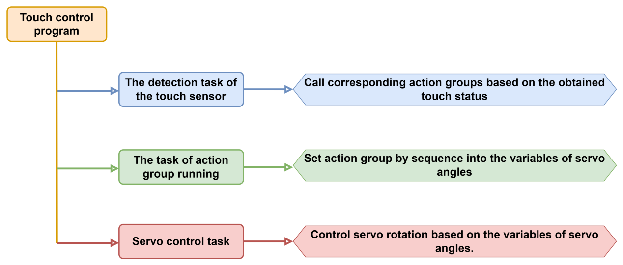
7.5.2 Touch Sensor
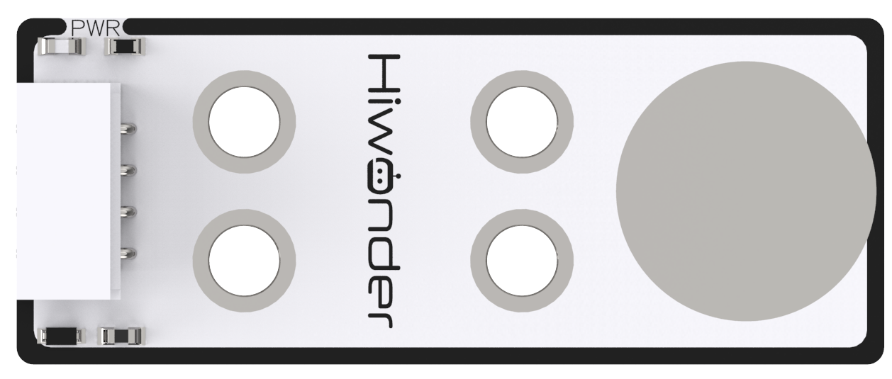
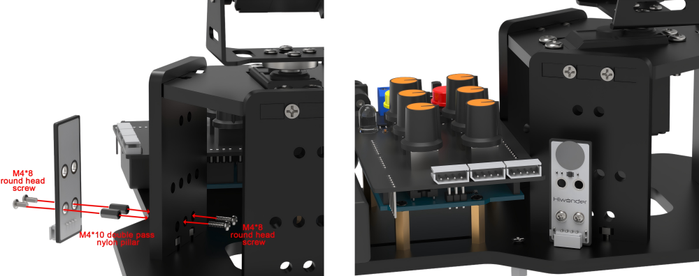
This is a touch sensor based on the principle of capacitance sensing, which mainly detects human touch or metal through gold-plated contact surface on the sensor.
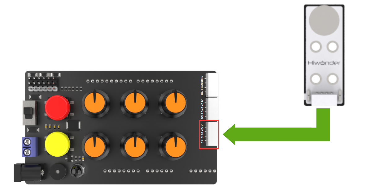
Wiring
Connect the ultrasonic module to D10 and D12 interface through 4Pin cable as pictured:
7.5.3 Program Download
Note
Remove the Bluetooth module before downloading the program, otherwise the serial interface conflict will lead to program download failure.
Please turn the switch of the battery box to “OFF” when connect Type-B download cable to avoid the cable touch the power pins of expansion board by mistake, which may cause a short circuit.
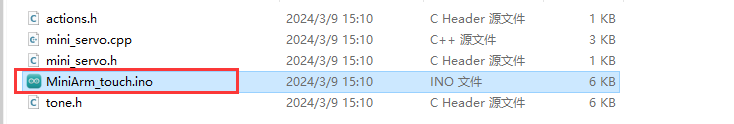
(1) Locate “MiniArm_Touch\MiniArm_touch.ino” program file in the same path as this document.
(2) Connect Arduino to the computer through UNO Type-B cable.
(3) Click “Select Development Board” option. The software will automatically test current Arduino serial port, then click to connect.

(4) Click  to download the program to Arduino, then wait for download to complete.


7.5.4 Program Outcome
After powering on, the robotic arm will return to the initial position and then proceed to preparatory action for grasping the block.
When you touch the metal surface of the sensor once, the buzzer on the expansion board will sound and the RGB light will turn red. After that, the robotic arm will execute the action group for grasping the block.
Once the arm has stopped running, touch the metal side of the sensor again, at which point the buzzer will sound again and place the cube on the left side of the arm. At this point, the RGB light on the expansion board will emits red.
7.5.5 Program Brief Analysis
Import Library File
6 7 8 9 | #include <FastLED.h> //import LED library #include <Servo.h> //import servo library #include "tone.h" //tone library #include "mini_servo.h" |
Import the library files required for this program, including the RGB control library and servo control library.
Define Pins and Create Objects
(1) Firstly, define the tones of the two buzzers and the Arduino pins connected to the hardware, mainly consist of six servo pins, one touch sensor pin, one buzzer pin and one RGB light pin.
11 12 13 14 15 16 17 18 | const static uint16_t DOC5[] = { TONE_C5 }; const static uint16_t DOC6[] = { TONE_C6 }; /* pin definition */ const static uint8_t servoPins[5] = { 7, 6, 5, 4, 3};//servo pin definition const static uint8_t touch = 12; const static uint8_t buzzerPin = 11; const static uint8_t rgbPin = 13; |
(2) Create the objects of the RGB light, action group control object and servo control object. Meanwhile, variables controlled by the servo are created. For example, limit_angle set angle limits for each joint of robotic arm, and the servo_angles array is used for storing actual angle of servo with range from 0 to 180.
20 21 22 23 24 25 26 27 28 29 30 | //RGB light control object static CRGB rgbs[1]; //action group control object HW_ACTION_CTL action_ctl; //servo control object Servo servos[5]; /* limit for each joint angle */ const uint8_t limt_angles[5][2] = {{0,82},{0,180},{0,180},{0,180},{0,180}}; /* the angle value actually controlled by serv */ static float servo_angles[5] = { 1,40,15,175,65,90 }; |
(3) In the mini_servo.h action group control object program, the constructor also define the extended_func_angles variable. That is the desired angle value of servo. Meanwhile, it declares relevant function used for controlling execute action group and reading deviation.
11 12 13 14 15 16 17 18 19 20 21 22 23 24 25 26 27 28 | class HW_ACTION_CTL{ public: /* the angle used in secondary development routine */ uint8_t extended_func_angles[5] = { 1,40,15,175,65,90 }; //control and perform action group void action_set(int num); int action_state_get(void); void action_task(void); void read_offset(void); int8_t* get_offset(void); private: //action group control variables int action_num = 0; int8_t servo_offset[5]; uint8_t eeprom_read_buf[16]; }; |
For the desired value and actual value, you can see the servo_control function called in the loop main function.
If you want the servo to approach to the target position gradually, call this line of code servo_angles[i] = servo_angles[i] * 0.85 + extended_func_angles[i] * 0.15 in the control task function.
This causes the servo to move each time by 85% of the actual value and 15% of the desired value, so that the actual value gets progressively closer to the desired value. When they are equal, the robotic arm stop moving.
167 168 169 170 171 172 173 174 175 176 177 178 179 180 181 182 | for (int i = 0; i < 5; ++i) {
if(servo_angles[i] > action_ctl.extended_func_angles[i])
{
servo_angles[i] = servo_angles[i] * 0.9 + action_ctl.extended_func_angles[i] * 0.1;
if(servo_angles[i] < action_ctl.extended_func_angles[i])
servo_angles[i] = action_ctl.extended_func_angles[i];
}else if(servo_angles[i] < action_ctl.extended_func_angles[i])
{
servo_angles[i] = servo_angles[i] * 0.9 + (action_ctl.extended_func_angles[i] * 0.1 + 1);
if(servo_angles[i] > action_ctl.extended_func_angles[i])
servo_angles[i] = action_ctl.extended_func_angles[i];
}
servo_angles[i] = servo_angles[i] < limt_angles[i][0] ? limt_angles[i][0] : servo_angles[i];
servo_angles[i] = servo_angles[i] > limt_angles[i][1] ? limt_angles[i][1] : servo_angles[i];
servos[i].write(i == 0 || i == 5 ? 180 - servo_angles[i] : servo_angles[i]);
}
|
(4) The following section declares task function used for executing different control task. The servo_control function is used for controlling servo, the play_tune() function is used for setting buzzer sound, the tune_task() function is used for controlling buzzer sound, the touch_task() is used for testing the touch sensor state and call execution action group.
37 38 39 40 | static void servo_control(void); /* servo control */ void play_tune(uint16_t *p, uint32_t beat, uint16_t len); /* buzzer control interface */ void tune_task(void); /* buzzer control task */ void touch_task(void); /* touch sensor detection task */ |
Initialization Settings
(1) Initialize related hardware equipment in setup() function. The first is serial interface, which sets the baud rate of communication to 115200 and the timeout for reading data to 500ms.
42 43 44 45 46 | void setup() { // put your setup code here, to run once: Serial.begin(115200); // set the elapsed time for reading data from the serial port Serial.setTimeout(500); |
(2) Assign servo IO port. Use the FastLED library to initialize RGB lights on expansion board, and connect it to RGB pin. Then set the color to green by rgbs[0] = CRGB(0, 255, 0) and use FastLED.show function to display the set color.
48 49 50 51 52 53 54 55 56 | // assign servo IO port for (int i = 0; i < 5; ++i) { servos[i].attach(servoPins[i],500,2500); } //initialize and control RGB light FastLED.addLeds<WS2812, rgbPin, GRB>(rgbs, 1); rgbs[0] = CRGB(0, 0, 100); FastLED.show(); |
(3) Initialize the touch sensor and read deviation data of servo.
58 59 60 61 | //initialize touch sensor pinMode(touch, INPUT); //read deviation data of servo action_ctl.read_offset(); |
(4) Set the pin of buzzer to output mode and call the tong() function to activate the buzzer. Then call the noTone() function to stop activating buzzer afteer a 100ms delay.
63 64 65 66 67 | //initialize buzzer and beep one time pinMode(buzzerPin, OUTPUT); tone(buzzerPin, 1000); delay(100); noTone(buzzerPin); |
Touch Sensor Detection Task
After initialization, call the ultrasonic task function touch_task in the loop main function, which is used for testing the state of touch sensor and calling action group by the state.
The function defines the variable last_tick firstly, which is mainly used for calculating the time interval.
Next, check if 100ms have passed since the last call to the ultrasound_task function. If it have passed, the following code is executed. Otherwise, the function returns directly. The millis function is the time since the Arduino board started. In this way, the function ensures that the task of detecting the distance is performed every 100ms.
Uses the digitalRead function to define the touch sensor as 0 when the metal face is pressed and 1 when the metal face is not pressed.
84 85 86 87 88 89 90 91 92 93 94 95 96 97 98 99 100 | // touch sensor detection task void touch_task(void) { static uint32_t last_tick = 0; static uint8_t step = 0; static uint8_t act_num = 0; static uint32_t delay_count = 0; static uint8_t turn; //current stage. 0 represents grasping stage; 1 represents placing stage static uint8_t stage = 0; // time interval is 100ms if (millis() - last_tick < 100) { return; } last_tick = millis(); |
Execution Feedback
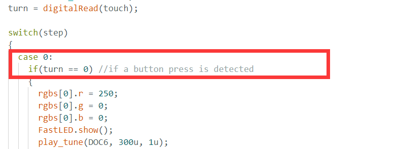
(1) Following the steps, firstly read the level of the touch sensor pin. If the value of the button is equal to 0, that is to say the button is pressed, the RGB lights up red. After the buzzer emits a beep, determine whether to enter the prevention stage or the grasping stage based on the “stage” variable. If entering the placing stage, set to call action group 2; if entering the grasping stage, set to call action group 1.
103 104 105 106 107 108 109 110 111 112 113 114 115 116 117 118 119 120 121 122 123 124 125 126 127 128 129 130 131 132 133 134 135 | turn = digitalRead(touch); switch(step) { case 0: if(turn == 0) //if a button press is detected { rgbs[0].r = 250; rgbs[0].g = 0; rgbs[0].b = 0; FastLED.show(); play_tune(DOC6, 300u, 1u); if(stage)//placing stage { act_num = 2; stage = 0; } else //grasping stage { act_num = 1; stage = 1; } count = 0; step++; } }else //if touch is not detected { rgbs[0].r = 0; rgbs[0].g = 0; rgbs[0].b = 0; FastLED.show(); } break; |
(2) Enter case 1 and perform delay wait based on the value of delay_count. Since each time enter the case 1, the tilt angle detection task is called. And 100ms delay is performed each time when you enter the button detection task. Therefore, the case 1 will delay for 1000ms firstly. Then the action group running flag is set by the action_set() function. After that, it will jump to the next stage.
136 137 138 139 140 141 142 143 144 145 146 | case 1: //wait for 1s and place the wood block to the specified position delay_count++; if(delay_count > 10) { delay_count = 0; // run action group action_ctl.action_set(act_num); act_num = 0; step++; } break; |
In the action group running task under the mini_servo.cpp file, the value of the action_num will be determined directly. If the value is not 0, the action group will run.
11 12 13 14 15 16 17 18 19 20 21 22 23 24 25 26 27 | class HW_ACTION_CTL{ public: /* the angle used in secondary development routine */ uint8_t extended_func_angles[5] = { 1,40,15,175,65,90 }; //control and perform action group void action_set(int num); int action_state_get(void); void action_task(void); void read_offset(void); int8_t* get_offset(void); private: //action group control variables int action_num = 0; int8_t servo_offset[5]; uint8_t eeprom_read_buf[16]; }; |
(3) Case 2 is the stage where it waits for the action to finish running. After completing the recognition, waiting, and calling the action group as mentioned above, it checks if the action_num variable is 0 to determine if the action group has finished running. After the action group finishes, the step stage variable is reset to 0.
147 148 149 150 151 152 153 154 155 | case 2: //wait for resetting the action state if(action_ctl.action_state_get() == 0) { step = 0; } break; default: step = 0; break; |
Servo Control Task
(1) In the servo control task, the same variable last_tick is used for delay processing.
159 160 161 162 163 164 165 | // servo control task void servo_control(void) { static uint32_t last_tick = 0; if (millis() - last_tick < 20) { return; } last_tick = millis(); |
(2) Next, get the desired value of the servo through action_ctl object. Note that the desired value at this point is the result of the desired value plus the deviation outcome of servo. So this desired value is the actual desired value. Finally, the actual desired value of the servo is assigned to the actual control angle. Then pass it to the servo object to actually control the rotation of the servo.
167 168 169 170 171 172 173 174 175 176 177 178 179 180 181 182 183 | for (int i = 0; i < 5; ++i) {
if(servo_angles[i] > action_ctl.extended_func_angles[i])
{
servo_angles[i] = servo_angles[i] * 0.9 + action_ctl.extended_func_angles[i] * 0.1;
if(servo_angles[i] < action_ctl.extended_func_angles[i])
servo_angles[i] = action_ctl.extended_func_angles[i];
}else if(servo_angles[i] < action_ctl.extended_func_angles[i])
{
servo_angles[i] = servo_angles[i] * 0.9 + (action_ctl.extended_func_angles[i] * 0.1 + 1);
if(servo_angles[i] > action_ctl.extended_func_angles[i])
servo_angles[i] = action_ctl.extended_func_angles[i];
}
servo_angles[i] = servo_angles[i] < limt_angles[i][0] ? limt_angles[i][0] : servo_angles[i];
servo_angles[i] = servo_angles[i] > limt_angles[i][1] ? limt_angles[i][1] : servo_angles[i];
servos[i].write(i == 0 || i == 5 ? 180 - servo_angles[i] : servo_angles[i]);
}
}
|
Let’s further explain the ideal desired value and actual desired value. In the action_ctl object, extended_func_angles is the ideal desired value, which excludes deviation due to servo structure. In the actual project,
servos often have a certain range of deviations due to their mechanical structure. To achieve more accurate control of the servo angle, we calculate the additional angle needed for the servo to reach the ideal position by adjusting for this deviation. This additional angle can be positive, negative, or zero. Then, during actual servo control, add this deviation value to the ideal expected angle, resulting in the actual expected angle.
7.5.6 Function Extension
The touching state of the touch sensor can be modified to a long press. The specific modifications can be referred in the following steps:
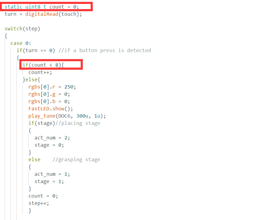
(1) Locate the section of the program that detects touch status. You can see that the sensor status is obtained firstly and assigned to the “turn” variable. Then, the touch sensor is detected by checking the value of “turn”.
(2) Here, we create a variable count as the fixed interval for detection. Firstly, at line 105, we detect the touch status for the first time, and then we check the value of the count variable. Each time the count is less than 8, it increments by 1. As we know from the previous content, the system delays by 100ms each time it reaches the button detection part. Therefore, when “count” equals to 8, it equivalent to 800ms delay. That is to say, after we press on the touch piece for about 800ms, the block will be picked up and placed in the action group on the left.
7.5.7 FAQ
Q: since the code was upload, touch sensor does not respond.
A: please check that you have connected the 4-pin cable to the correct IO interface.
Q: the touch sensor is sometimes accurate when touched, and sometimes inaccurate.
A: Please ensure that the sensor contact surface or your fingers are not contaminated.
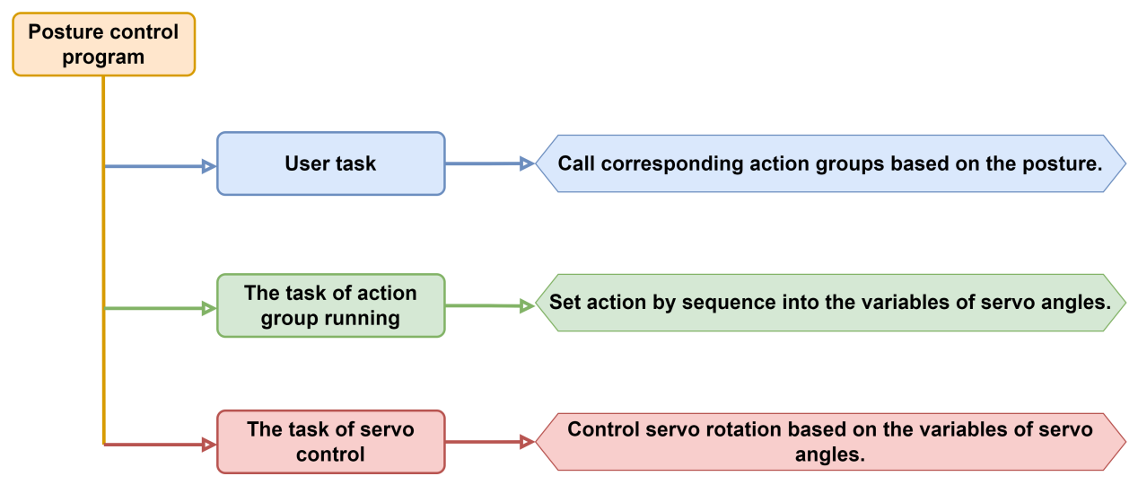
7.6 PostureControl
In this section, you will learn how to use the touch sensor to test touch state. And how to use it to realize the action of touching the robotic arm to grasp the square, then to place the square. Meanwhile, control the RGB light to change color.
7.6.1 Program Flowchart
7.6.2 Acceleration Sensor
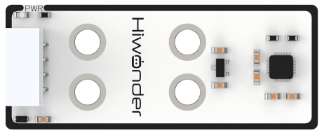
This sensor primarily utilizes the MPU6050 sensor component. It integrates a 3-axis MEMS gyroscope, a 3-axis MEMS accelerometer, and an expandable Digital Motion Processor (DMP).
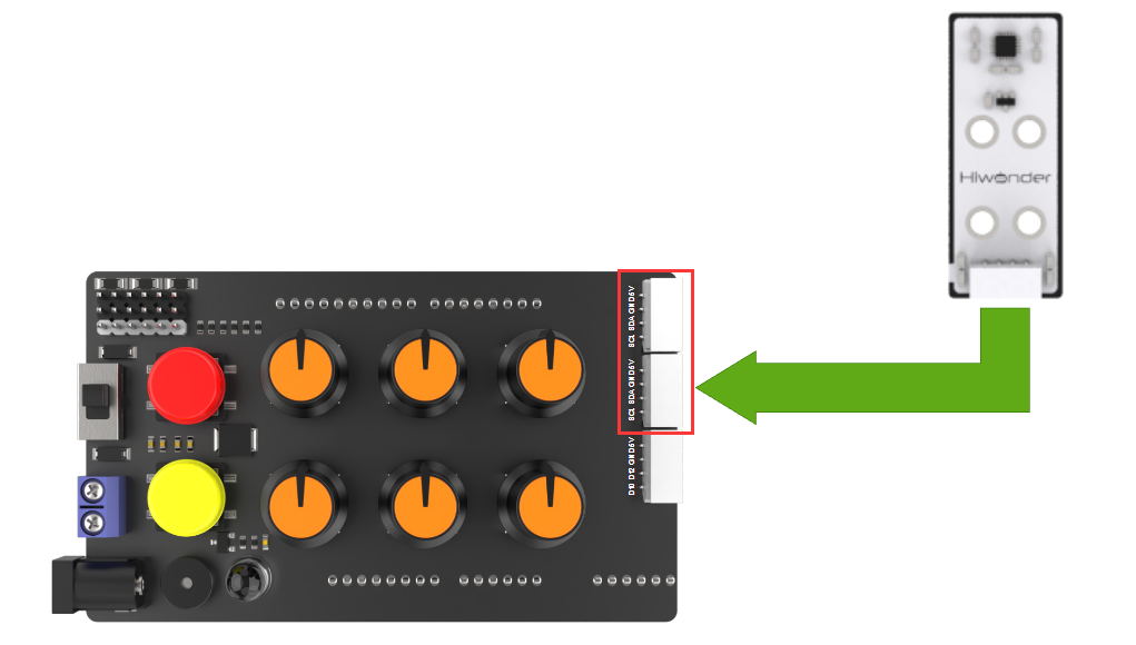
Sensor Wiring
Connect the accelerometer to any I2C interface through 4Pin cable.
7.6.3 Program Download
Note
Remove the Bluetooth module before downloading the program, otherwise the serial interface conflict will lead to program download failure.
Please turn the switch of the battery box to “OFF” when connect Type-B download cable to avoid the cable touch the power pins of expansion board by mistake, which may cause a short circuit.
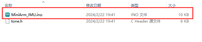
(1) Locate “MiniArm_IMU.ino” program file in the same path as document “Program File/MiniArm_IMU”.
(2) Connect Arduino to the computer through UNO Type-B cable.

(3) Click “Select Development Board” option. The software will automatically test current Arduino serial port, then click to connect.

(4) Click  to download the program to Arduino, then wait for download to complete.


7.6.4 Program Outcome
After powering on, the robotic arm will return to the initial position and then proceed to preparatory action for grasping the block.
Taking the “hiwonder” label on the accelerometer as the positive direction, tilt the accelerometer downwards while holding it. After a beep from the MiniArm buzzer, the robotic arm will grasp the block.
Taking the “hiwonder” label on the accelerometer as the positive direction, tilt the accelerometer to the left while holding it. After a beep from the MiniArm buzzer, the robotic arm will grasp the cube and place it in the left side of the arm.
Taking the “hiwonder” label on the accelerometer as the positive direction, tilt the accelerometer to the right while holding it. After a beep from the MiniArm buzzer, the robotic arm will grasp the cube and place it in the right side of the arm.
7.6.5 Program Brief Analysis
Import Library File
7 8 9 10 11 | #include <FastLED.h> //import LED library #include <Servo.h> //import servo library #include "tone.h" //tone library #include <MPU6050.h> #include "mini_servo.h" |
Import the RGB control library, servo control library, tone library, accelerometer sensor library and robotic arm control library.
Define Pins and Create Objects
(1) Create variables related to the MPU6050 accelerometer. Among them, “ax”, “ay”, and “az” represent the values of the tilt angles in the three-axis directions, while “gx”, “gy”, and “gz” represent the values of acceleration in the three-axis directions. The “radianX_last” represents the final tilt angle obtained in the X-axis direction, while “radianY_last” represents the final tilt angle obtained in the Y-axis direction.
13 14 15 16 17 18 19 20 21 22 23 24 25 26 27 28 | MPU6050 accelgyro; int16_t ax, ay, az; int16_t gx, gy, gz; float ax0, ay0, az0; float gx0, gy0, gz0; float ax1, ay1, az1; float gx1, gy1, gz1; float dx; float dz; int ax_offset, ay_offset, az_offset, gx_offset, gy_offset, gz_offset; float radianX; float radianY; float radianZ; float radianX_last; //final obtained X-axis inclination float radianY_last; //final obtained Y-axis inclination |
(2) Define the tones of the two buzzers and the Arduino pins connected to the hardware. It mainly consist of six servo pins, one buzzer pin and one RGB light pin.
39 40 41 42 43 44 45 46 47 48 49 | //RGB light control object static CRGB rgbs[1]; //action group control object HW_ACTION_CTL action_ctl; //servo control object Servo servos[5]; /* limit for each joint angle */ const uint8_t limt_angles[5][2] = {{0,90},{0,180},{0,180},{0,180},{0,180}}; /* the angle value actually controlled by servo */ static float servo_angles[5] = { 80,15,175,65,90 }; |
(3) Create the objects of the RGB light, action group control object and servo control object. Meanwhile, variables controlled by the servo are created. For example, limit_angle set angle limits for each joint of robotic arm, and the servo_angles array is used for storing actual angle of servo with range from 0 to 180.
(4) In the constructor of the action group object, the extended_func_angles is defined. That is the desired angle value of servo. Meanwhile, it declares relevant function used for controlling execute action group.
11 12 13 14 15 16 17 18 19 20 21 22 23 24 25 26 27 | class HW_ACTION_CTL{ public: /* the angle used in the secondary development routines */ uint8_t extended_func_angles[5] = { 80,15,175,65,90 }; //control execute action group void action_set(int num); int action_state_get(void); void action_task(void); void read_offset(void); int8_t* get_offset(void); private: //action group control variables int action_num = 0; int8_t servo_offset[5]; uint8_t eeprom_read_buf[16]; }; |
For the desired value and actual value, there may be difference in the subsequent control of servo rotation due to numerical differences. You can see the servo_control function called in the loop main function specifically.
If you want the servo to approach to the target position gradually, call this line of code servo_angles[i] = servo_angles[i] * 0.85 + extended_func_angles[i] * 0.15 in the control task function.
This causes the servo to move each time by adding a portion of the servo pulse-width of the desired value to its previous position. After each movement, the current new data will be reassigned. This enables the robotic arm to stop moving when the target position is reached.
255 256 257 258 259 260 261 262 263 264 265 266 267 268 269 270 271 272 | for (int i = 0; i < 5; ++i) {
if(servo_angles[i] > action_ctl.extended_func_angles[i])
{
servo_angles[i] = servo_angles[i] * 0.9 + action_ctl.extended_func_angles[i] * 0.1;
if(servo_angles[i] < action_ctl.extended_func_angles[i])
servo_angles[i] = action_ctl.extended_func_angles[i];
}else if(servo_angles[i] < action_ctl.extended_func_angles[i])
{
servo_angles[i] = servo_angles[i] * 0.9 + (action_ctl.extended_func_angles[i] * 0.1 + 1);
if(servo_angles[i] > action_ctl.extended_func_angles[i])
servo_angles[i] = action_ctl.extended_func_angles[i];
}
servo_angles[i] = servo_angles[i] < limt_angles[i][0] ? limt_angles[i][0] : servo_angles[i];
servo_angles[i] = servo_angles[i] > limt_angles[i][1] ? limt_angles[i][1] : servo_angles[i];
servos[i].write(i == 0 || i == 5 ? 180 - servo_angles[i] : servo_angles[i]);
}
}
|
(5) Task functions are used for executing different control task. The “servo_control” function is used for controlling servo, the play_tune() function is used for setting buzzer sound, the tune_task() function is used for controlling buzzer sound, action_task() function is used for calling action group running, and the update_mpu6050() is used for updating the obtained data of accelerometer.
57 58 59 60 61 62 | static void servo_control(void); /* servo control */ void play_tune(uint16_t *p, uint32_t beat, uint16_t len); /* buzzer control interface */ void tune_task(void); /* buzzer control task */ void user_task(void); /* user task */ void update_mpu6050(void); /*update inclination sensor data*/ |
Initialization Settings
(1) The setup() function is used for initializing the relevant hardware devices. First is the serial port, set the baud rate for communication to 115200 and the read data timeout to 500ms.
64 65 66 67 68 | void setup() { // put your setup code here, to run once: Serial.begin(115200); // set the read data timeout of serial port Serial.setTimeout(500); |
(2) Assign the servo IO port, use the FastLED library to initialize the RGB light on the expansion board and connect it to the RGB pin. Set the RGB color to green through rgbs[0] = CRGB(0, 255, 0). Finally, use the FastLED.show function to display the set color.
70 71 72 73 74 75 76 77 78 | // assign servo IO port for (int i = 0; i < 5; ++i) { servos[i].attach(servoPins[i],500,2500); } //initialize the RGB light and control it FastLED.addLeds<WS2812, rgbPin, GRB>(rgbs, 1); rgbs[0] = CRGB(0, 0, 100); FastLED.show(); |
(3) Set the buzzer interface to output mode and call the tone() function to make the buzzer sound. Call noTone() function to stop sounding the buzzer after a delay of 100ms. Then read the deviation data of servo.
80 81 82 83 84 85 86 87 | //initialize buzzer and beep one time pinMode(buzzerPin, OUTPUT); tone(buzzerPin, 1000); delay(100); noTone(buzzerPin); //read deviation data of servo action_ctl.read_offset(); |
Create an object for the accelerometer, set the ranges for angular velocity and acceleration, obtain data from each axis, and finally calibrate the data.
89 90 91 92 93 94 95 96 97 98 99 100 101 | //MPU6050 configuration Wire.begin(); accelgyro.initialize(); accelgyro.setFullScaleGyroRange(3); //set the range of angular velocity accelgyro.setFullScaleAccelRange(1); //set the range of acceleration delay(200); accelgyro.getMotion6(&ax, &ay, &az, &gx, &gy, &gz); //get current data for each axis to calibrate ax_offset = ax; //X-axis acceleration calibration data ay_offset = ay; //Y-axis acceleration calibration data az_offset = az - 8192; //Z-axis acceleration calibration data gx_offset = gx; //X-axis angular velocity calibration data gy_offset = gy; //Y-axis angular velocity calibration data gz_offset = gz; //Z-axis angular velocity calibration data |
User Task
After initialization, call the ultrasonic task function touch_task in the loop main function, which is used for adjusting action group to control the robotic arm based on the tilted angle of accelerometer. The function defines the variable last_tick firstly, which is mainly used for calculating the time interval.
120 121 122 123 124 125 126 127 128 129 130 131 132 133 | // user task void user_task(void) { static uint32_t last_tick = 0; static uint8_t step = 0; static uint8_t act_num = 0; static uint32_t delay_count = 0; int color = 0; // time interval 100ms if (millis() - last_tick < 100) { return; } last_tick = millis(); |
Next, check if 100ms have passed since the last call to the ultrasound_task function. If it have passed, the following code is executed. Otherwise, the function returns directly. The millis function is the time since the Arduino board started. In this way, the function ensures that the task of detecting the distance is performed every 100ms.
Then, get filtered ultrasonic measurements through the ul.Filter function, and store the outcome in the variable “dis”.
Execution Feedback
(1) Following the steps, detect the downward tilt angle of the accelerometer in the X-axis direction firstly. If the tilt angle is greater than 40, the RGB on the control expansion board lights up red, and the buzzer beeps once to record the action group that needs to be called for action group 1. That action group is the robotic arm grasps the block. If there is no tilt or the tilt angle is too small, the robotic arm will not respond.
135 136 137 138 139 140 141 142 143 144 145 146 147 148 149 150 151 152 153 154 | switch(step) { case 0: if(radianX_last > 40) //grasp { rgbs[0].r = 100; //red rgbs[0].g = 0; rgbs[0].b = 0; FastLED.show(); play_tune(DOC6, 300u, 1u); // action group 1 needs to be executed for sorting act_num = 1; step++; }else{ //if it is not detected rgbs[0].r = 0; rgbs[0].g = 0; rgbs[0].b = 0; FastLED.show(); } break; |
(2) Enter case 1 and perform delay wait based on the value of delay_count. Since each time enter the case 1, the tilt angle detection task is called. And 100ms delay is performed each time when you enter the button detection task. Therefore, the case 1 will delay for 1000ms firstly. Then set the number of action group and running it. After that, it will jump to the next stage.
155 156 157 158 159 160 161 162 163 164 165 | case 1: //wait for 1s and place the wood block to the correct position. delay_count++; if(delay_count > 5) { delay_count = 0; // run action group action_ctl.action_set(act_num); act_num = 0; step++; } break; |
(3) Case 2 is the stage where it waits for the action to finish running. After completing the recognition, waiting, and calling the action group as mentioned above, it checks if the action_num variable is 0 to determine if the action group has finished running. After the action group finishes, enter the next stage.
166 167 168 169 170 171 | case 2: //wait for resetting the action state if(action_ctl.action_state_get() == 0) { step++; } break; |
(4) Case 3 is the stage detects tilt angle of the accelerometer in the Y-axis direction, which also means the left and right direction.
172 173 174 175 176 177 178 179 180 181 182 183 184 185 186 187 188 189 190 191 192 193 194 | case 3: if(radianY_last > 50) //right { rgbs[0].r = 0; rgbs[0].g = 100; rgbs[0].b = 0; FastLED.show(); play_tune(DOC6, 300u, 1u); // action group 2 needs to be executed for sorting action_ctl.action_set(2); step++; }else if(radianY_last < -50) //left { rgbs[0].r = 0; rgbs[0].g = 0; rgbs[0].b = 100;//blue FastLED.show(); play_tune(DOC6, 300u, 1u); // action group 3 needs to be executed for sorting action_ctl.action_set(3); step++; } break; |
When the tilt angle of the accelerometer Y-axis is greater than 50, the acceleration sensor tilts to the left and RGB light up green. After emitting a beep from the buzzer, record the required action group as action group 2, which means placing block to the left.
When the tilt angle of the accelerometer Y-axis is less than -50, the acceleration sensor tilts to the right and RGB light up blue. After emitting a beep from the buzzer, record the required action group as action group 3, which means placing block to the right.
(5) Case 4 is the stage waiting for the action status to be cleared. When the action group finishes running, the RGB light on the expansion board will be cleared. And the variable of the current stage of “step” will be set to 0, and the execution will start from stage 0 again.
195 196 197 198 199 200 201 202 203 204 205 206 | case 4: //wait for resetting the action state if(action_ctl.action_state_get() == 0) { FastLED.clear(); step = 0; } break; default: step = 0; break; } } |
Servo Control Task
(1) In the servo control task, the same variable last_tick is used for delay processing.
247 248 249 250 251 252 253 | // 舵机控制任务(不需修改)(servo control task (no need to modify))
void servo_control(void) {
static uint32_t last_tick = 0;
if (millis() - last_tick < 20) {
return;
}
last_tick = millis();
|
(2) Next, get the desired value of the servo through action_ctl object. Note that the desired value at this point is the result of the desired value plus the deviation outcome of servo. So this desired value is the actual desired value. Finally, the actual desired value of the servo is assigned to the actual control angle. Then pass it to the servo object to actually control the rotation of the servo.
255 256 257 258 259 260 261 262 263 264 265 266 267 268 269 270 271 272 | for (int i = 0; i < 5; ++i) {
if(servo_angles[i] > action_ctl.extended_func_angles[i])
{
servo_angles[i] = servo_angles[i] * 0.9 + action_ctl.extended_func_angles[i] * 0.1;
if(servo_angles[i] < action_ctl.extended_func_angles[i])
servo_angles[i] = action_ctl.extended_func_angles[i];
}else if(servo_angles[i] < action_ctl.extended_func_angles[i])
{
servo_angles[i] = servo_angles[i] * 0.9 + (action_ctl.extended_func_angles[i] * 0.1 + 1);
if(servo_angles[i] > action_ctl.extended_func_angles[i])
servo_angles[i] = action_ctl.extended_func_angles[i];
}
servo_angles[i] = servo_angles[i] < limt_angles[i][0] ? limt_angles[i][0] : servo_angles[i];
servo_angles[i] = servo_angles[i] > limt_angles[i][1] ? limt_angles[i][1] : servo_angles[i];
servos[i].write(i == 0 || i == 5 ? 180 - servo_angles[i] : servo_angles[i]);
}
}
|
Let’s further explain the ideal desired value and actual desired value. In the action_ctl object, extended_func_angles is the ideal desired value, which excludes deviation due to servo structure. In the actual project,
servos often have a certain range of deviations due to their mechanical structure. To achieve more accurate control of the servo angle, we calculate the additional angle needed for the servo to reach the ideal position by adjusting for this deviation. This additional angle can be positive, negative, or zero. Then, during actual servo control, add this deviation value to the ideal expected angle, resulting in the actual expected angle.
7.6.6 Function Extension
We can modify the condition to: if (radianX_last < -40), so that when the accelerometer sensor tilts towards the negative direction of the X-axis, the grabbing action will be executed.
  switch(step)
  {
    case 0:
      if(radianx_last >40) //grasp
        {
          rgbs[0].r = 100; //red
          rgbs[0].g = 0;
          rgbs[0].b = 0;
          FastLED.show();
          play_tune(DOC6,300u,1u);
          // action group 1 needs to be executed for sorting
          act_num = 1;
          step++;
        }else{ //if it is not detected
          rgbs[0].r = 0;
          rgbs[0].g = 0;
          rgbs[0].b = 0;
          FastLED.show();
        }
        break;
7.6.7 FAQ
Q: since the code was upload, the gyroscope accelerometer sensor is not responding to rotation.
A: please check that you have connected the 4-pin cable to the I2C interface and turn the knob on the expansion board to the initial position.
Q: the gyroscope accelerometer sensor is tilted but not responding.
A: please ensure that the sensor is in a horizontal position before use.
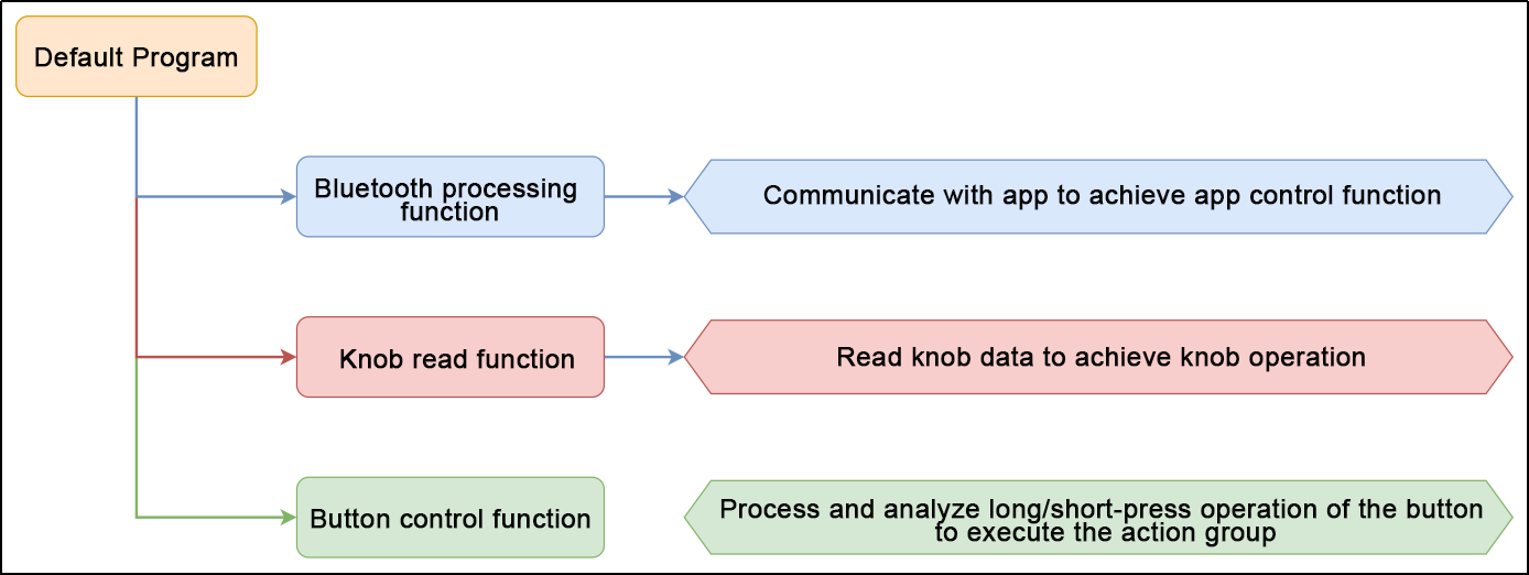
7.7 APP Remote Control
This section mainly explains the function realization for the control program of the robotic hand. Therefore, you can better understand and write the program.
7.7.1 Program Flowchart
7.7.2 Program Download
Note
Remove the Bluetooth module before downloading the program. Or the program will fail to download because of the serial port conflict.
Please switch the battery box to the “OFF” when connecting the Type-B cable. This action prevents the download cable from accidentally touching the power pins of the expansion board, which may cause a short circuit.
(1) Locate and open “miniArm/miniArm.ino” program file in the same directory as this section.
(2) Connect Arduino to the computer with the UNO data cable (Type-B).

(3) Click “Select Board”, and the software will automatically detect the current Arduino serial port. Next, click to connect.
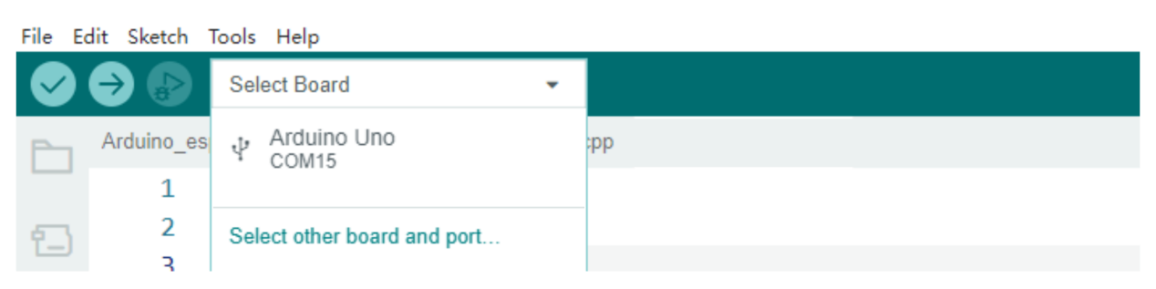
(4) Click  to download the program into Arduino. Then just wait for it to complete.


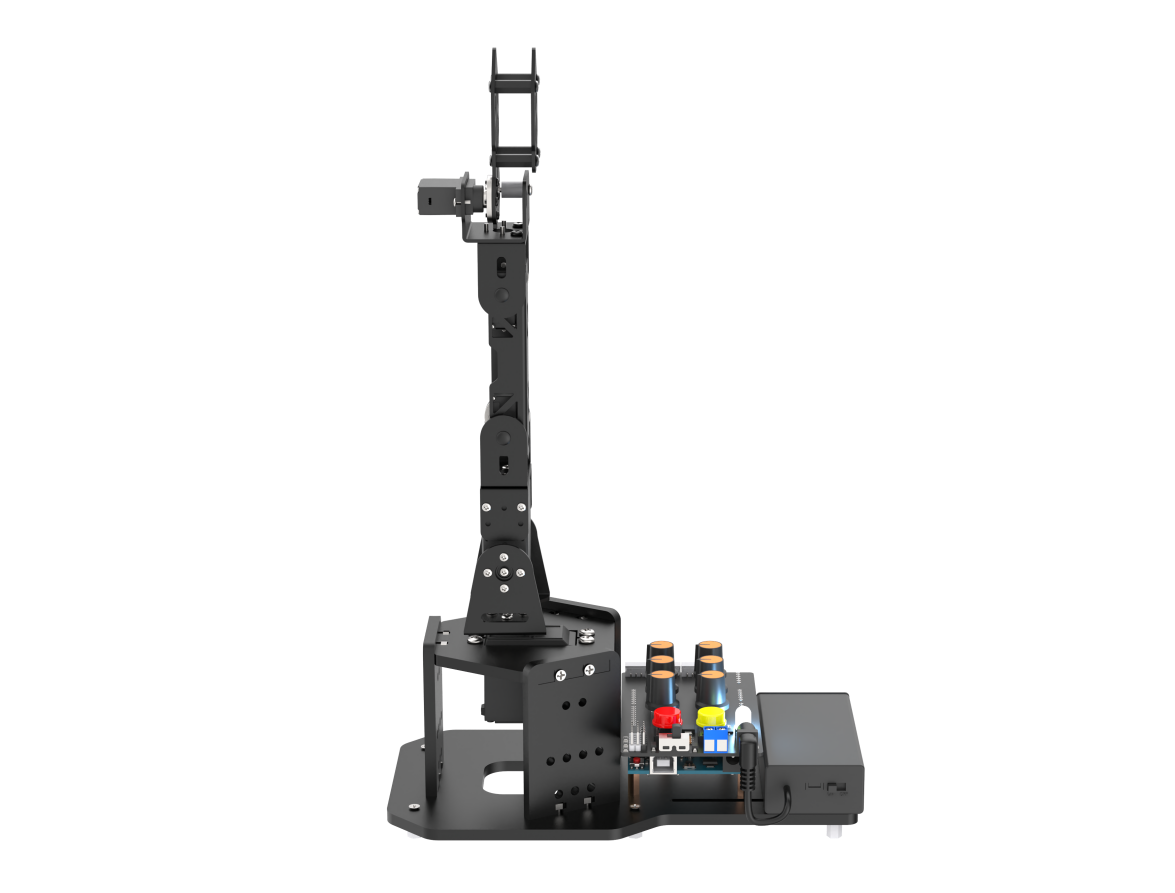
7.7.3 Program Outcome
(1) When powered on, the robotic arm returns to the initial position. At the same time, the RGB light on the expansion board turns white, which is the neutral position program.
(2) Press both buttons simultaneously for 1 second until RGB light turns green. This indicates that miniArm has unlocked the neutral position function and entered the knob control game.
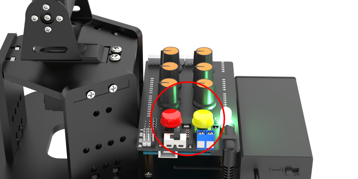
(3) Long press K1 to clear the previous action group first and enter the action group editing mode. Then use the knob to control the position of the robotic hand and press K1 to record the current position into action group. Next, long press K1 to exit the action group editing mode and save the edited action group into “Falsh”. Then short press K2 to execute the action group.
(4) When you plug in the Bluetooth module and connect it to the app, the robotic hand enters the Bluetooth control game.
7.7.4 Brief Program Analysis
Servo Neutral Function “servos_middle()”
“servos_middle()” is a function that puts all servos in the middle position, which is executed within the “set_up()” function. To produce a neutral installation environment, it can be removed in the subsequent program.
The procedure is as follows:
① Read the current deviation angle;
② Set all the servos to the neutral angle;
③ Detect current button state in a loop:
(1) Press K1 button for more than two seconds to enter deviation adjustment. At this point, you can rotate the knobs to return the servo to the initial position. Then long press K2 for more than two seconds, the adjusted position will be preserved.
(2) When two buttons are pressed at the same time for about two seconds, the loop will exit and the function will exit;
(3) When two buttons are not pressed at the same time or the count of pressed buttons does not reach two seconds, the count is cleared and the loop will continue.
115 116 117 118 119 120 121 122 123 124 125 126 127 128 129 130 131 132 133 134 135 136 137 138 139 140 141 142 143 144 145 146 147 148 149 150 151 152 153 154 155 156 157 158 159 160 161 162 163 164 165 166 167 168 169 170 171 172 173 174 175 176 177 178 179 180 181 182 183 184 185 186 187 188 189 190 191 192 193 194 195 196 197 198 | void servos_middle(void)
{
// 读取偏差角度(read deviation angle)
for (int i = 0; i < 16; ++i) {
eeprom_read_buf[i] = EEPROM.read(EEPROM_SERVO_OFFSET_START_ADDR + i);
}
if (strcmp(eeprom_read_buf, EEPROM_START_FLAG) == 0) {
// Serial.println("EEPROM read");
memset(eeprom_read_buf, 0 , sizeof(eeprom_read_buf));
for (int i = 0; i < 6; ++i) {
eeprom_read_buf[i] = EEPROM.read(EEPROM_SERVO_OFFSET_DATA_ADDR + i);
}
memcpy(servo_offset , eeprom_read_buf , 6);
}
int16_t set_angles = 0;
// 设置舵机为中位角度(set servo to the neutral position angle)
for (int i = 0; i < 5; ++i) {
set_angles = 90 + servo_offset[i];
set_angles = set_angles < limt_angles[i][0] ? limt_angles[i][0] : set_angles;
set_angles = set_angles > limt_angles[i][1] ? limt_angles[i][1] : set_angles;
servos[i].write(i == 0 || i == 5 ? 180 - set_angles : set_angles);
}
uint16_t step = 0 , i = 0 , count[2] = {0,0};
// 循环检测,若2个按键同时按下1s时间,则跳出中位任务(detect in a loop; if both of the two buttons are pressed for 1 second, jump out the nuetral position)
while(true)
{
for(i = 0 ; i < 2 ; i++)
{
if(!digitalRead(keyPins[i]))
count[i] = count[i] > 500 ? 500 : count[i]+1;
else
count[i] = 0;
}
switch(step)
{
case 0: //获取按键值(obtain the button value)
if(count[0] > LONG_PRESS && count[1] > LONG_PRESS-50)
{
// 计算偏差(calculate deviation)
for(i = 0; i < 6 ; i++){
servo_offset[i] = knob_angles[i] - 90 + servo_offset[i];
}
for (int j = 0; j < strlen(EEPROM_START_FLAG) + 1; ++j) { /* 存储空间已初始化标志(the storage space has initialized the flag) */
EEPROM.write(EEPROM_SERVO_OFFSET_START_ADDR + j, EEPROM_START_FLAG[j]);
}
memcpy(eeprom_read_buf , (uint8_t*)servo_offset , 6);
// memset(eeprom_read_buf , 0 , sizeof(eeprom_read_buf)); //清除偏移量(clear the offset)
for (int k = 0; k < 6; ++k) {// 保存偏差(save the deviation)
EEPROM.write(EEPROM_SERVO_OFFSET_DATA_ADDR + k, eeprom_read_buf[k]);
}
return;
}else if(count[0] > LONG_PRESS) //单独长按K1,则跳入偏移调节(only long press K1 to jump into offset adjustment)
{
step = 1;
FastLED.clear(); //绿色(green)
rgbs[0].g = 100;
FastLED.show();
}
break;
case 1: //调节偏差(adjustment deviation)
knob_update(); // 旋钮读取更新(updata knob read)
servo_control(); // 舵机控制(servo contorl)
if(count[1] > LONG_PRESS) //跳出调节模式(jump out the adjustment mode)
{
FastLED.clear(); //白色(white)
rgbs[0].r = 100;
rgbs[0].g = 100;
rgbs[0].b = 100;
FastLED.show();
step = 0;
}
break;
default:
step = 0;
break;
}
delay(10);
}
}
|
Bluetooth Handling Function “recv_handler()”
recv_handler() is a handling function that receive Bluetooth serial port information resolution and control the robotic arm.
Program analysis:
Read serial port information until encountering the ‘$’ symbol, then stop reading and check the first character:
① When the first character is ‘A’ ~ ‘F’, the corresponding arm servo movement is controlled;
200 201 202 203 204 205 206 207 208 209 210 211 212 213 214 215 216 217 218 219 220 221 222 223 224 225 226 227 228 | void recv_handler(void) { while (Serial.available() > 0) { String cmd = Serial.readStringUntil('$'); switch (cmd[0]) { case 'A': app_angles[0] = atoi(cmd.c_str() + 1); g_mode = MODE_APP; break; case 'B': app_angles[1] = atoi(cmd.c_str() + 1); g_mode = MODE_APP; break; case 'C': app_angles[2] = atoi(cmd.c_str() + 1); g_mode = MODE_APP; break; case 'D': app_angles[3] = atoi(cmd.c_str() + 1); g_mode = MODE_APP; break; case 'E': app_angles[4] = atoi(cmd.c_str() + 1); g_mode = MODE_APP; break; case 'F': app_angles[5] = atoi(cmd.c_str() + 1); g_mode = MODE_APP; break; |
②When the first character is ‘G’ ~ ‘J’, the color of RGB light is controlled;
229 230 231 232 233 234 235 236 237 238 239 240 241 242 243 244 | case 'G': g_mode = MODE_APP; rgbs[0].r = atoi(cmd.c_str() + 1); break; case 'H': g_mode = MODE_APP; rgbs[0].g = atoi(cmd.c_str() + 1); break; case 'I': g_mode = MODE_APP; rgbs[0].b = atoi(cmd.c_str() + 1); break; case 'J': g_mode = MODE_APP; FastLED.show(); break; |
③When the first character is ‘Z’, the buzzer sound is controlled.
245 246 247 248 249 250 251 252 253 254 255 256 257 258 259 | case 'Z': { g_mode = MODE_APP; if (cmd[1] == '1') { play_tune(DOC6, 10000u, 1u); } if (cmd[1] == '0') { play_tune(DOC6, 1u, 0u); } break; } default: break; } } |
Knob Reading Function “knob_update()”
knob_update() is a function that reads values of 5 knob potentiometers, and controls the position of the corresponding servo based on this value.
The program logic is as follows:
① Read the analog value of each potentiometer, and obtain the expected value of the knob by weighted calculation.
② Map the expected value of the knob to the range of 0 to 180 degrees of the servo, read the current knob value and store it.
③ If the difference between the current knob value and the next read value is 5, it will enter the knob mode. For example, in the current app mode, when you rotate the knob a difference will occur. At this time, the robotic arm will enter the knob mode and will not disconnect with the app. Using the app again will return to app control mode. If it is not rotated and the knob value does not change, it will not enter the knob mode.
④ If currently in knob mode, assign the servo angle mapped to the current value of the knob to the servo. Then the servo will rotate to the corresponding angle.
269 270 271 272 273 274 275 276 277 278 279 280 281 282 283 284 285 286 287 288 289 290 291 292 293 294 295 296 297 298 | void knob_update(void) { /* 旋钮读取更新(updata knob read) */
static uint32_t last_tick = 0;
static float values[6];
float angle = 0;
if (millis() - last_tick < 10) {
return;
}
last_tick = millis();
values[0] = values[0] * 0.7 + analogRead(A0) * 0.3;
values[1] = values[1] * 0.7 + analogRead(A1) * 0.3;
values[2] = values[2] * 0.7 + analogRead(A2) * 0.3;
values[3] = values[3] * 0.7 + analogRead(A3) * 0.3;
values[4] = values[4] * 0.7 + analogRead(A4) * 0.3;
values[5] = values[5] * 0.7 + analogRead(A5) * 0.3;
for (int i = 0; i < 6; ++i) {
angle = map(values[i], 0, 1023, 0, 180);
angle = angle < 0 ? 0 : (angle > 180 ? 180 : angle);
if (fabs(angle - knob_angles[i]) > 5 && g_mode != MODE_KNOB) { /* 当发现旋钮被旋转超过阈值则恢复旋钮控制模式(可能处于手机app控制模式)(When it is detected that the knob has been rotated beyond the threshold, the knob control mode is restored (which may be in the app control mode)) */
g_mode = MODE_KNOB;
action_group_running_step = 0;
rgbs[0].r = 0;
rgbs[0].g = 255;
rgbs[0].b = 0;
FastLED.show();
}
if (g_mode == MODE_KNOB) {
knob_angles[i] = angle;
}
}
}
|
Servo Control Function “servo_control()”
servo_control() is a function that actually controls servo. This function enters every 25ms. Depending on the mode, it calculates the actual angle value for each servo and ultimately assigns it to the PWM control function to control the servo angle.
Because servo No.0 has the opposite mechanical angle compared to the other servos, a flip needs to be performed here.
302 303 304 305 306 307 308 309 310 311 312 313 314 315 316 317 318 319 320 321 322 323 324 325 326 327 328 329 330 331 332 333 334 335 336 337 338 339 | void servo_control(void) {
static uint32_t last_tick = 0;
static uint8_t tmp_angles = 0;
static int16_t set_angles = 0;
if (millis() - last_tick < 20) {
return;
}
last_tick = millis();
for (int i = 0; i < 5; ++i) {
if (g_mode == MODE_APP) {
tmp_angles = app_angles[i];
} else if (g_mode == MODE_KNOB) {
tmp_angles = knob_angles[i];
} else if (g_mode == MODE_EXTENDED) {
tmp_angles = extended_func_angles[i];
} else{
tmp_angles = action_angles[i];
}
if(servo_angles[i] > tmp_angles)
{
servo_angles[i] = servo_angles[i] * 0.9 + tmp_angles * 0.1;
if(servo_angles[i] < tmp_angles)
servo_angles[i] = tmp_angles;
}else if(servo_angles[i] < tmp_angles)
{
servo_angles[i] = servo_angles[i] * 0.9 + (tmp_angles * 0.1 + 1);
if(servo_angles[i] > tmp_angles)
servo_angles[i] = tmp_angles;
}
set_angles = servo_angles[i] + servo_offset[i];
set_angles = set_angles < limt_angles[i][0] ? limt_angles[i][0] : set_angles;
set_angles = set_angles > limt_angles[i][1] ? limt_angles[i][1] : set_angles;
servos[i].write(i == 0 || i == 5 ? 180 - set_angles : set_angles);
}
}
|
Buzzer-Related Function
(1) tune_task() is buzzer sound task function. According to the parameters set by the play_tune() function, the programmed tone arrays is played sequentially.
341 342 343 344 345 346 347 348 349 350 351 352 353 354 355 356 357 358 | void tune_task(void) { static uint32_t l_tune_beat = 0; static uint32_t last_tick = 0; // 若未到定时时间 且 响的次数跟上一次的一样(if it is not yet the scheduled time and the ringing duration is the same as the previous time) if (millis() - last_tick < l_tune_beat && tune_beat == l_tune_beat) { return; } l_tune_beat = tune_beat; last_tick = millis(); if (tune_num > 0) { tune_num -= 1; tone(buzzerPin, *tune++); } else { noTone(buzzerPin); tune_beat = 10; l_tune_beat = 10; } } |
(2) play_tune() function is an interface function used for setting the buzzer sound. You can call this function to set buzzer sound. Parameter 1 means the array of tones to be played; parameter 2 means the duration for each tone sounding; parameter 3 means the number of tones contained within the array.
360 361 362 363 364 | void play_tune(uint16_t *p, uint32_t beat, uint16_t len) { tune = p; tune_beat = beat; tune_num = len; } |
Action Group Running Function “action_group_task()”
action_group_task() function is used for executing action groups, which is running in the “loop()” circulation.
The function logic is as follows:
① When the action_group_running_step is 0, the action group will not be executed.
② When the action_group_running_step function is 1 or 2, the action group will start running the action group. First, all actions within the action group are read. Then, determine whether there is an action in the action group. If there is an action, assign “action_group_running_step” to 3~5, and the program proceeds to the next step for execution.
376 377 378 379 380 381 382 383 384 385 386 387 388 389 390 391 392 393 394 395 396 397 398 399 400 401 402 403 404 405 406 | switch (action_group_running_step) { case 0: break; case 1: case 2: { g_mode = MODE_ACTIONGROUP; action_index = 0; action_num = 0; for (int i = 0; i < 16; ++i) { eeprom_read_buf[i] = EEPROM.read(i); } if (strcmp(eeprom_read_buf, EEPROM_START_FLAG) == 0) { action_num = EEPROM.read(EEPROM_ACTION_NUM_ADDR); if (action_num > 0) { tick_wait = 1000; action_index = 0; if (action_group_running_step == 1) { action_group_running_step = 3; } if (action_group_running_step == 2) { action_group_running_step = 4; } } else { action_group_running_step = 0; } } else { action_group_running_step = 0; } break; } |
③ Run each read action sequentially until the action group execution is complete. Then assign action_group_running_step to 6 and the program proceed to the next step.
407 408 409 410 411 412 413 414 415 416 417 418 419 420 421 422 423 424 425 426 427 428 | case 3: case 4: case 5: { memset(eeprom_read_buf, 0, 16); for (int i = 0; i < EEPROM_ACTION_UNIT_LENGTH; ++i) { eeprom_read_buf[i] = EEPROM.read(EEPROM_ACTION_START_ADDR + EEPROM_ACTION_UNIT_LENGTH * action_index + i); } for (int i = 0; i < 6; ++i) { action_angles[i] = eeprom_read_buf[i]; } action_index += 1; if (action_index >= action_num) { if (action_group_running_step == 4) { action_group_running_step = 4; action_index = 0; } else { action_group_running_step = 6; } } break; } |
④ Illuminate the RGB light with green and jump back to the first step, stopping the action group.
429 430 431 432 433 434 435 436 437 438 | case 6: action_group_running_step = 0; tick_wait = 50; rgbs[0].r = 0; rgbs[0].g = 255; rgbs[0].b = 0; FastLED.show(); break; default: break; |
Button Handling Function “key_scan()”
key_scan() function is used for scanning button signal and calling corresponding program. The program flow is as follows:
① Read the button state firstly. Then enter state machine to call the corresponding state.
453 | uint16_t io = digitalRead(keyPins[i]); |
② When in the released state, no action is taken.
457 458 459 460 461 462 463 464 | case 0: { /* 松开普通状态下(under the normal releasing state) */ if (state) { key_step[i] = 1; pressed_tick[i] = last_tick; } break; } |
③ When short press K1, it is checked whether the system is in action group editing mode. If it is in the editing state, the arm will sounds once and you can add new motion. If it is not in the editing state, the arm stops running the action group and sounds a long beep.
469 470 471 472 473 474 475 476 477 478 479 480 481 482 483 484 | if (i == 0) //K1 { if (learning) { /* 增加新动作(add new action) */ memcpy(&action_group[action_index++], knob_angles, 6); play_tune(DOC5, 100, 1); } else { /* 停止动作组运行(stop action group running) */ if (action_group_running_step != 0) { action_group_running_step = 0; play_tune(DOC6, 800, 1); rgbs[0].r = 0; rgbs[0].g = 255; rgbs[0].b = 0; FastLED.show(); } } } |
When short press k2 and it is not in the action group editing mode, run action group and sound a beep.
485 486 487 488 489 490 491 492 493 494 495 496 497 | if (i == 1) //K2
{
if (!learning) { /* 单次运行动作组(run action group for a single time) */
if (action_group_running_step == 0) {
action_group_running_step = 1;
play_tune(DOC6, 100u, 1u);
rgbs[0].r = 255;
rgbs[0].g = 200;
rgbs[0].b = 0;
FastLED.show();
}
}
}
|
④ When long press K1, preserve the action group if it is in the action editing mode. Open action group editing mode if it is not in this mode.
498 499 500 501 502 503 504 505 506 507 508 509 510 511 512 513 514 515 516 517 518 519 520 521 522 523 524 525 526 527 528 529 530 | } else { if (last_tick - pressed_tick[i] > 1000) //若是长按(if it is a long press) { key_step[i] = 2; if (i == 0) { if (learning) { /* 退出动作编辑模式但不保存(exit the action editing mode but not save) */ for (int j = 0; j < action_index; ++j) { /* 保存动作组到EEPROM(save the action group to EEPROM) */ for (int k = 0; k < 6; ++k) { EEPROM.write(EEPROM_ACTION_START_ADDR + EEPROM_ACTION_UNIT_LENGTH * j + k, action_group[j][k]); } } EEPROM.write(EEPROM_ACTION_NUM_ADDR, action_index); /* 保存动作组包含的动作个数(save the number of actions included in the action group) */ for (int j = 0; j < strlen(EEPROM_START_FLAG) + 1; ++j) { /* 存储空间已初始化标志(the initialized flag for storage space) */ EEPROM.write(0 + j, EEPROM_START_FLAG[j]); } learning = false; play_tune(MI_RE_DO, 150, 3); rgbs[0].r = 0; rgbs[0].g = 255; rgbs[0].b = 0; FastLED.show(); } else { /* 进入动作编辑模式(enter the action group editing mode) */ if (action_group_running_step == 0) { learning = true; action_index = 0; play_tune(DO_RE_MI, 150, 3); rgbs[0].r = 255; rgbs[0].g = 0; rgbs[0].b = 0; FastLED.show(); } } } |
When long press K2, exit the action group editing mode and sound a short beep if it is in this mode. If it is not in this mode, run the action group in a loop.
531 532 533 534 535 536 537 538 539 540 541 542 543 544 545 546 547 548 549 550 551 | if (i == 1) { if (learning) { /* 退出动作编辑模式并保存(exit the action editing mode and save) */ learning = false; play_tune(MI_RE_DO, 150, 3); rgbs[0].r = 0; rgbs[0].g = 255; rgbs[0].b = 0; FastLED.show(); } else { if (action_group_running_step == 0) { /* 循环运行动作组(run action group in a loop) */ play_tune(DOC6, 300u, 1u); rgbs[0].r = 255; rgbs[0].g = 200; rgbs[0].b = 0; FastLED.show(); action_group_running_step = 2; /* 循环运行(run in a loop) */ } } } |