1. Getting Ready
1.1 miniArm Introduction
1.1.1 Product Introduction
Powered by Arduino UNO development board, miniArm robotic arm uses Arduino for programming. Equipped with UNO 6-channal knob expansion board and Bluetooth module, it can control the robotic arm using knob or app quickly and easily. And using a 7.4V lithium battery allows the robotic arm to be used anywhere.
There are IO and I2C connectors reserved. You can develop more interesting and fun creative projects pairing with sensor expansion kits.

1.1.2 Notes
Instructions on the usage and storage of this product:
(1) This product contains small components and sharp pins, making it unsuitable for children under 12 years old.
(2) Minors should use this product under the supervision and guidance of adults.
(3) This product contains small and sharp parts. Do not swallow or press them to avoid injury.
(4) This product includes conductive components. Do not touch them with metal objects when the power is on.
(5) Do not force the robot to move when it is powered on to avoid damage.
(6) If the product is not used for a long time, please charge the battery fully. Then, remove and store it in a cool and dry place.
1.1.3 Copyright Notice
This tutorial is the exclusive property of Shenzhen Hiwonder Technology Co., Ltd. No unit or individual is allowed to excerpt, copy, translate or disseminate the contents of this tutorial without permission.
Our company reserves the right to pursue legal responsibility against any unit or individual who infringes the copyright of this reference material.
1.1.4 Disclaimer
The product described in this manual, including hardware and software, are provided “as is”. While every effort has been made to ensure the accuracy of the content, the manual cannot guarantee that there are no errors or omissions. The information will undergo regular checks and any suggestions for improvement from our users are welcome. As the content of the product may change with the product version upgrade, please contact customer service when ordering to obtain the latest product information.
In addition, unless Hiwonder has expressly stated that the product has a certain use, we are not responsible for any damage or loss caused by the malfunction or damage of the product when used in extreme circumstances.
1.2 Packing List
(1) miniArm Starter Packing List
| No. | Components | Quantity | Picture |
|---|---|---|---|
| 1 | miniArm robotic arm(assembled) | 1 | 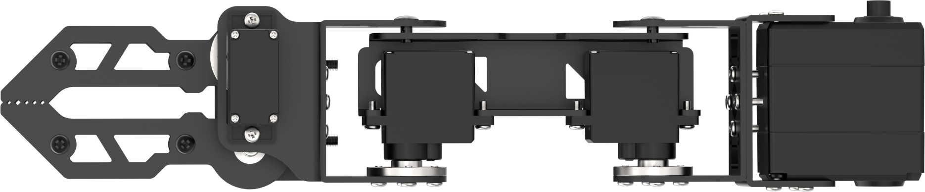 |
| 2 | Base U-shaped bracket | 1 | 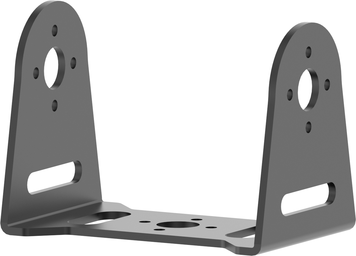 |
| 3 | Large bottom plate | 1 | 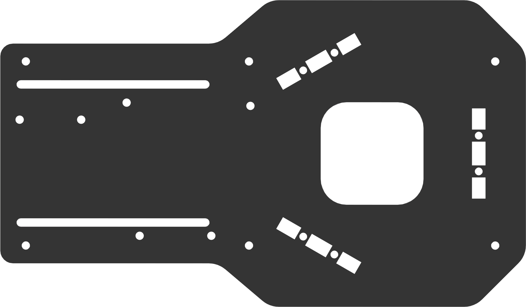 |
| 4 | Steering gear board | 1 | 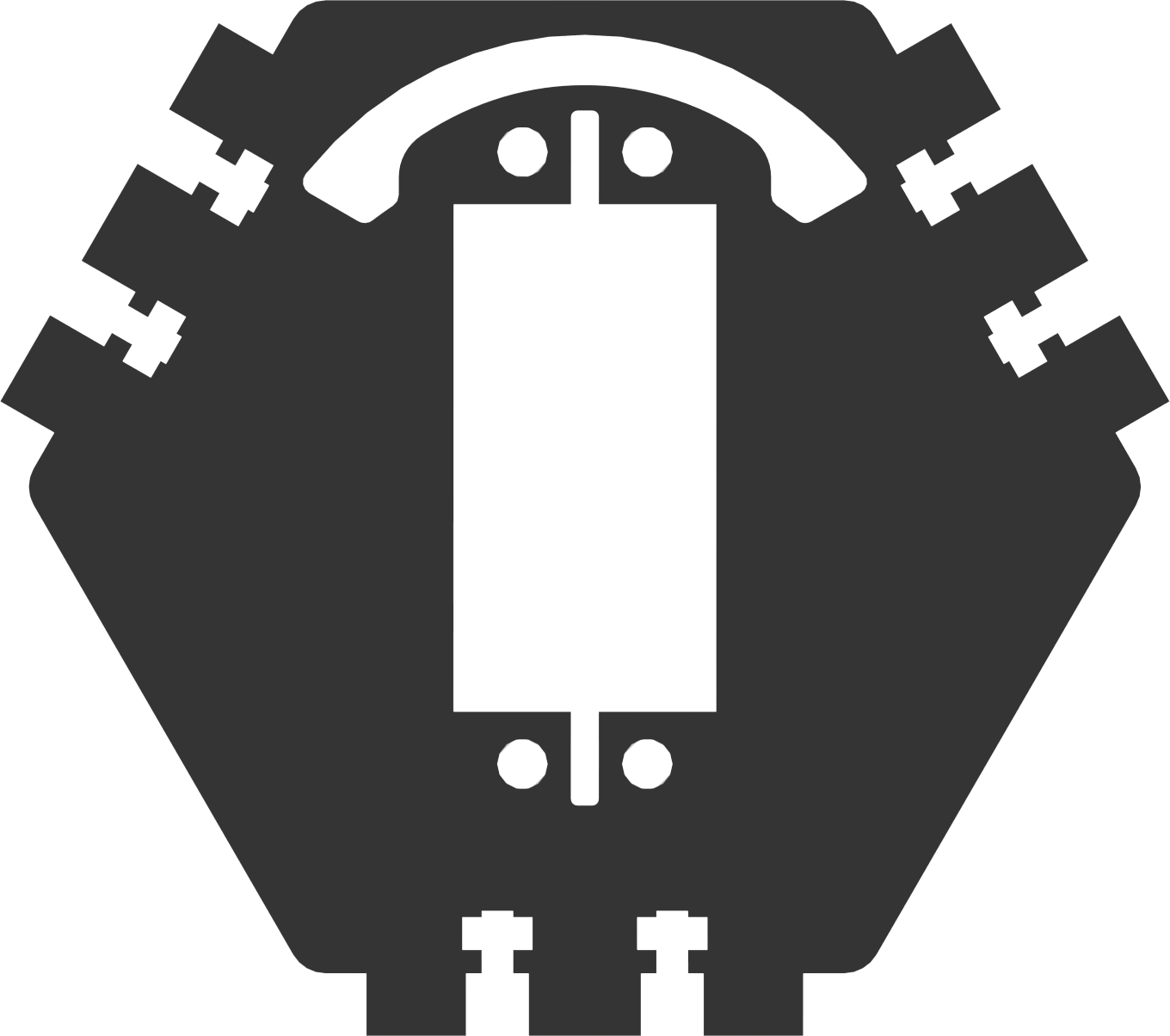 |
| 5 | Square plate | 3 | 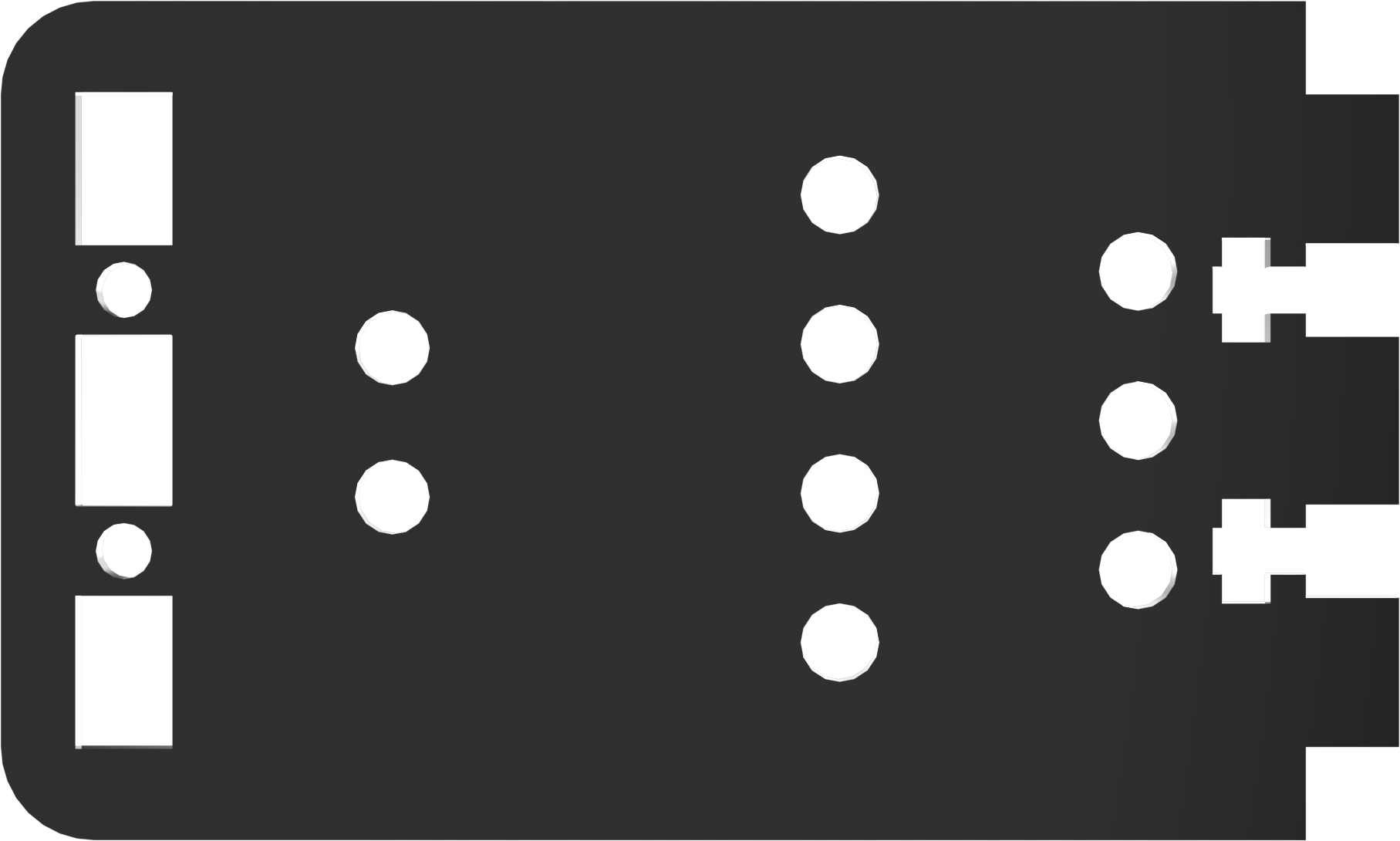 |
| 6 | LD-1501MG | 1 | 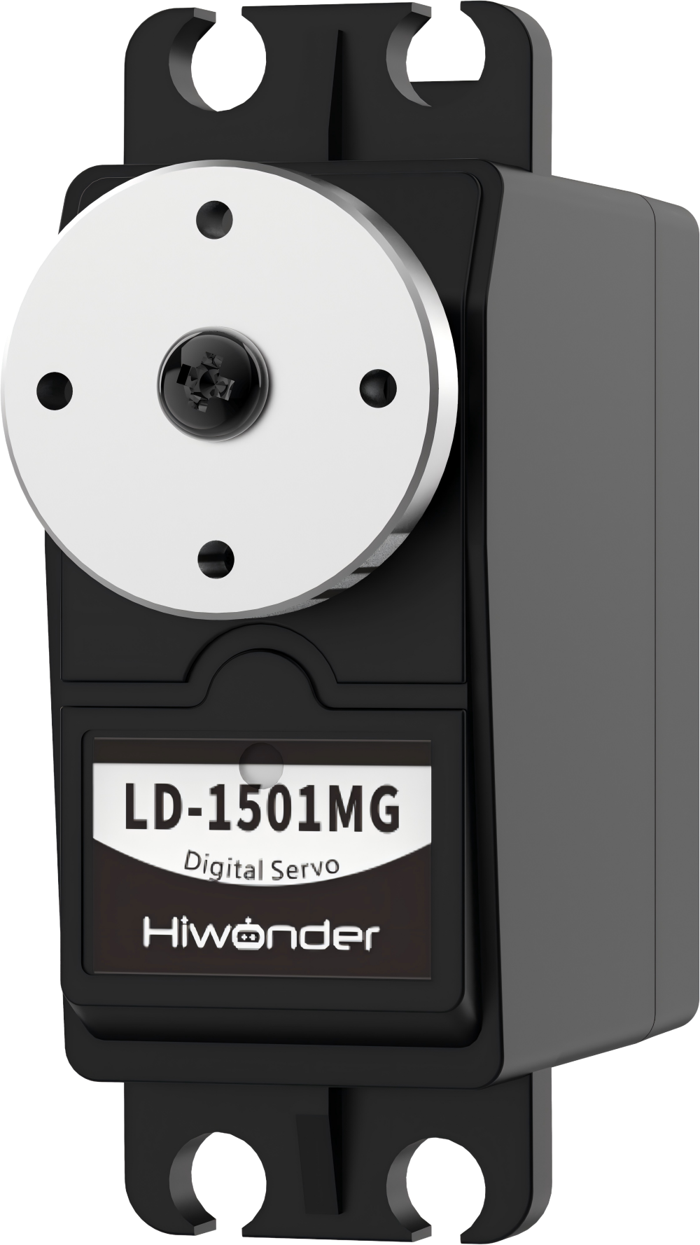 |
| 7 | UNO 6-channel knob expansion board | 1 | 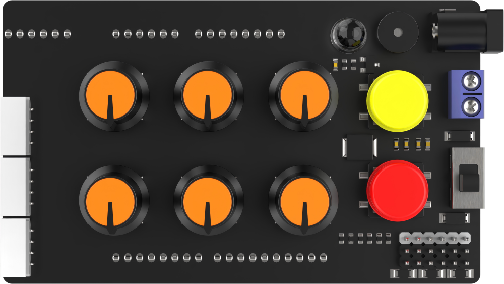 |
| 8 | Arduino UNO | 1 | 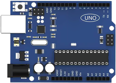 |
| 9 | USB square port | 1 | 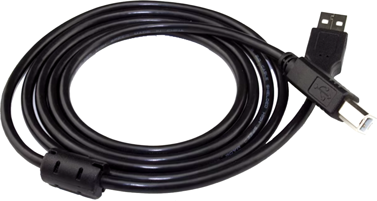 |
| 10 | Bluetooth module | 1 | 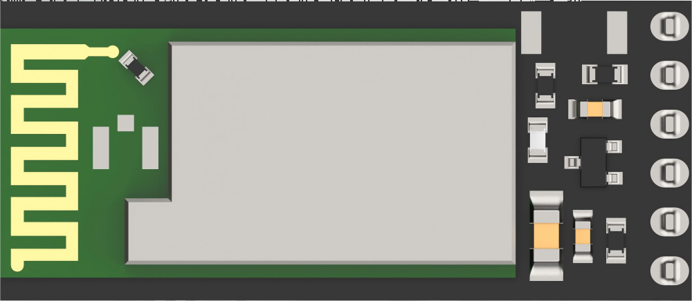 |
| 11 | charger | 1 | 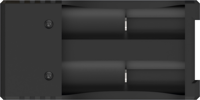 |
| 12 | Battery box | 1 | 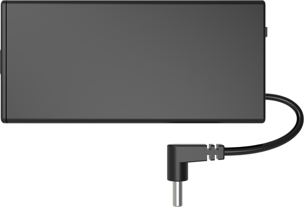 |
| 13 | 18650 LiPo battery | 2 |  |
| 14 | 35mm EVA Blocks | 2 |  |
| 15 | USB data cable | 1 |  |
| 16 | Accessory bag (screwdriver * 1 M315 Double-pass Copper Column * 2 M38 Double-pass nylon Column * 8 M36 Black round head screw * 6 M26 Round head screw * 6 A26 Round head self-tapping screw * 6 M310 flat head screw * 30 M3 nut * 20) |
1 | 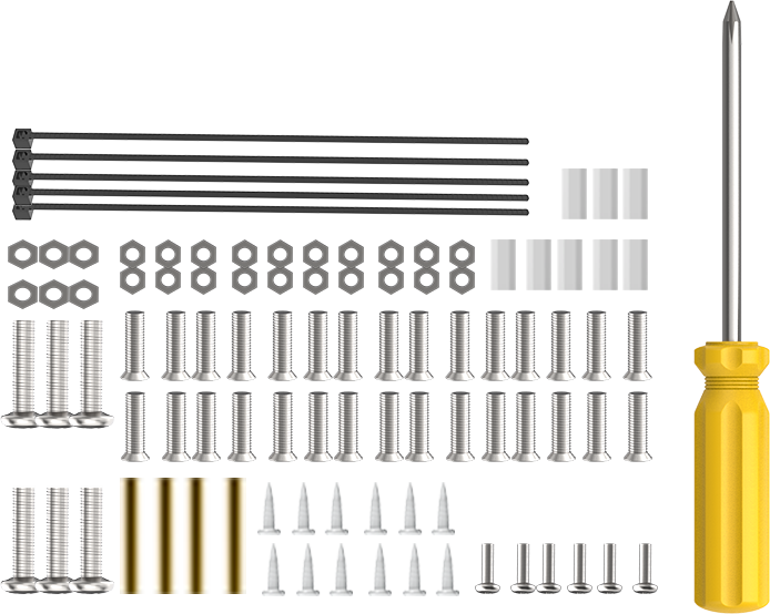 |
(2) miniArm Standard Packing List
| No. | Components | Quantity | Picture |
|---|---|---|---|
| 1 | miniArm robotic arm(assembled) | 1 | |
| 2 | Base U-shaped bracket | 1 | |
| 3 | Large bottom plate | 1 | |
| 4 | Steering gear board | 1 | |
| 5 | Square plate | 3 | |
| 6 | LD-1501MG | 1 | |
| 7 | UNO 6-channel knob expansion board | 1 | |
| 8 | Arduino UNO | 1 | |
| 9 | USB square port | 1 | |
| 10 | Bluetooth module | 1 | |
| 11 | charger | 1 | |
| 12 | Battery box | 1 | |
| 13 | 18650 LiPo battery | 2 | |
| 14 | 35mm EVA Blocks | 2 | |
| 15 | USB data cable | 1 | |
| 16 | Accessory bag (screwdriver * 1 M315 Double-pass Copper Column * 2 M38 Double-pass nylon Column * 8 M36 Black round head screw * 6 M26 Round head screw * 6 A26 Round head self-tapping screw * 6 M310 flat head screw * 30 M3 nut * 20) |
1 | |
| 17 | Glowing ultrasonic sensor | 1 | 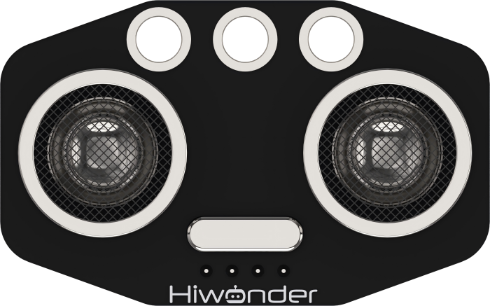 |
| 18 | Touch sensor | 1 | 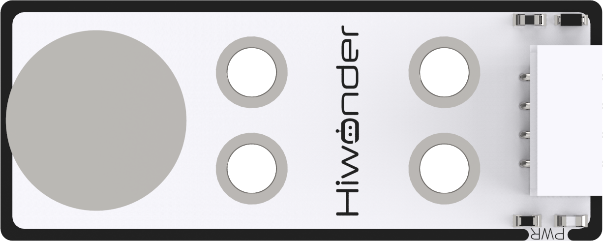 |
| 19 | Acceleration sensor | 1 | 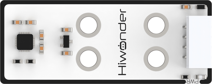 |
| 20 | ESP32Cam Module | 1 | 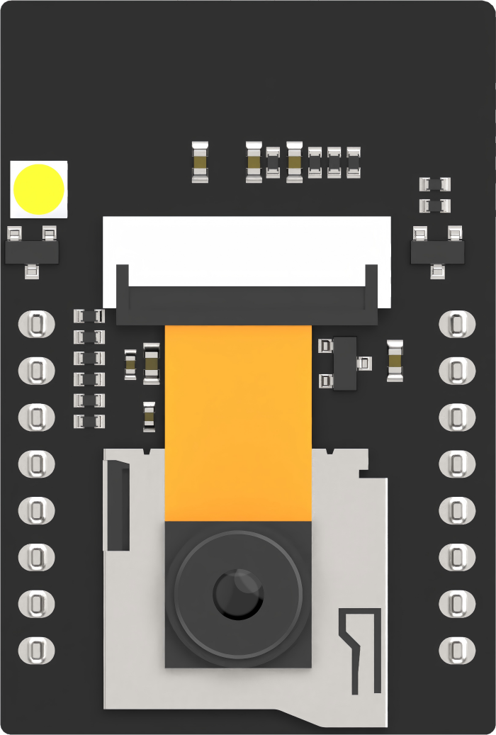 |
| 21 | Type-C data cable | 1 | 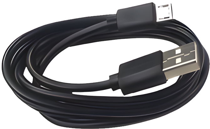 |
| 22 | 100mm 4PIN wire | 4 | 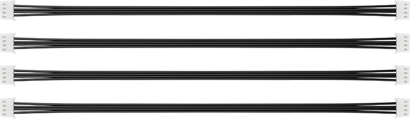 |
| 23 | Standard version accessory bag (M48 round head screw * 16 M410 Double-pass nylon Column * 4 M4*30 Double-pass nylon Column * 2) |
1 | 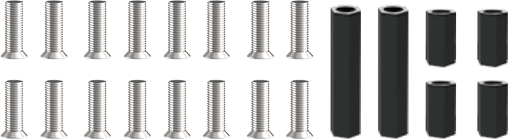 |
1.3 Assembly Instruction
This lesson takes miniArm starter installation as an example. The installation method is also applicable to other versions.
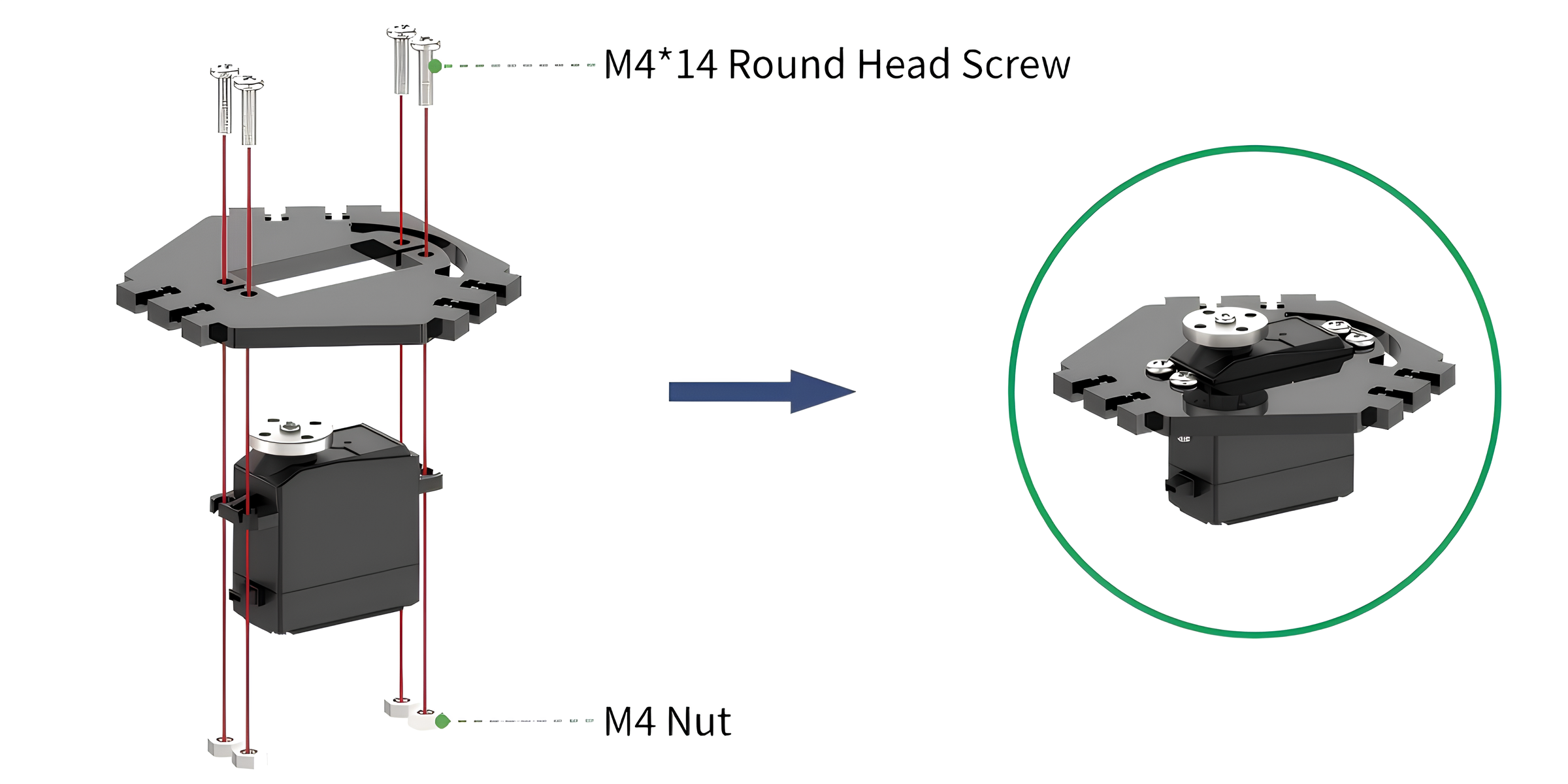
(1) Install the servo to servo board with four M4*14 round head screws and four M4 nuts. During installation, please ensure that the servo horn is kept away from side with the arc-shaped holes.
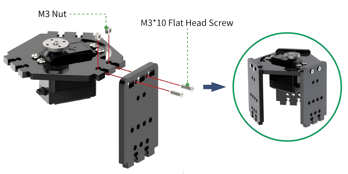
(2) Install the square board to the servo board with two M3*10 flat head screws and two M3 nuts. When installing, first put the M3 nut into the servo board holes, and then use one finger to hold it in place to prevent the nut from falling out. Next, insert the square board into the servo board, and finally use M3*10 flat head screws to secure it.
Install another two square boards in the same way. The installation is completed as follows:
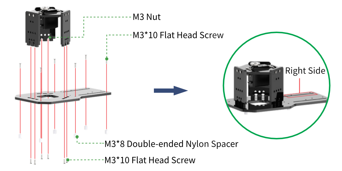
(3) Secure the square board on the baseboard with six M3*10 flat head screws and six M3 nuts.
And secured six M3*8 double-ended nylon spacers beneath the baseboard with six M3*10 flat head screws.
Note
Take the pan-tilt as the first view. The baseboard with less holes are located in the right side of the hand.
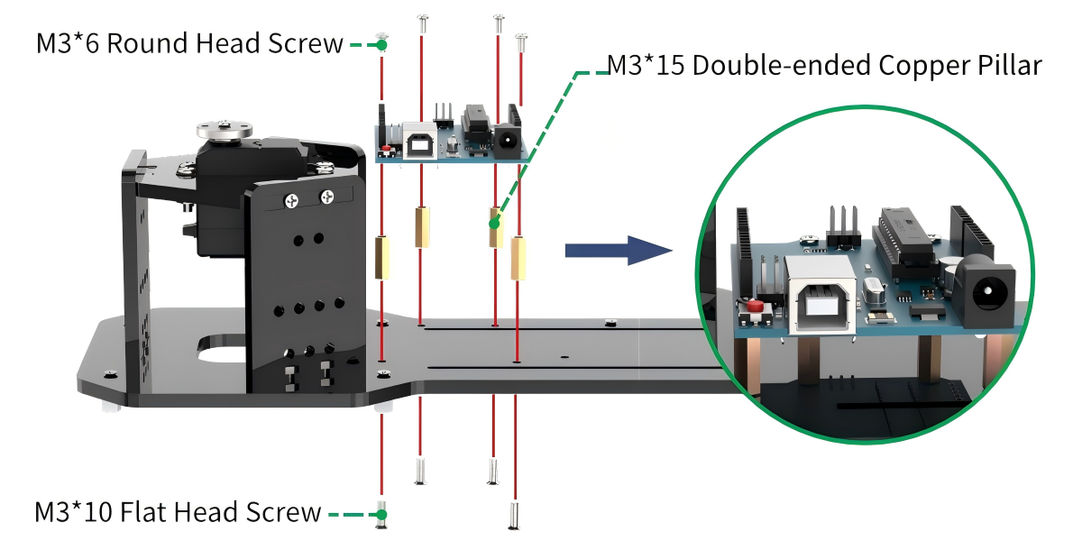
(4) Secured four M3*10 double-ended copper pillars on the Arduino UNO board with four M3*6 round head screws.
Then secured the board on the baseboard with four M3*10 flat head screws.
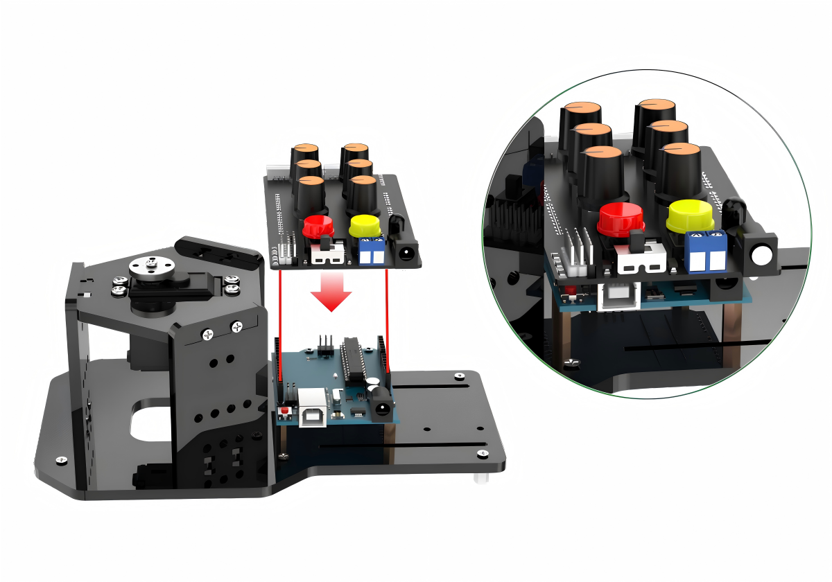
(5) Align the pins on the expansion board with the socket connectors of the board and insert them into the board one by one.
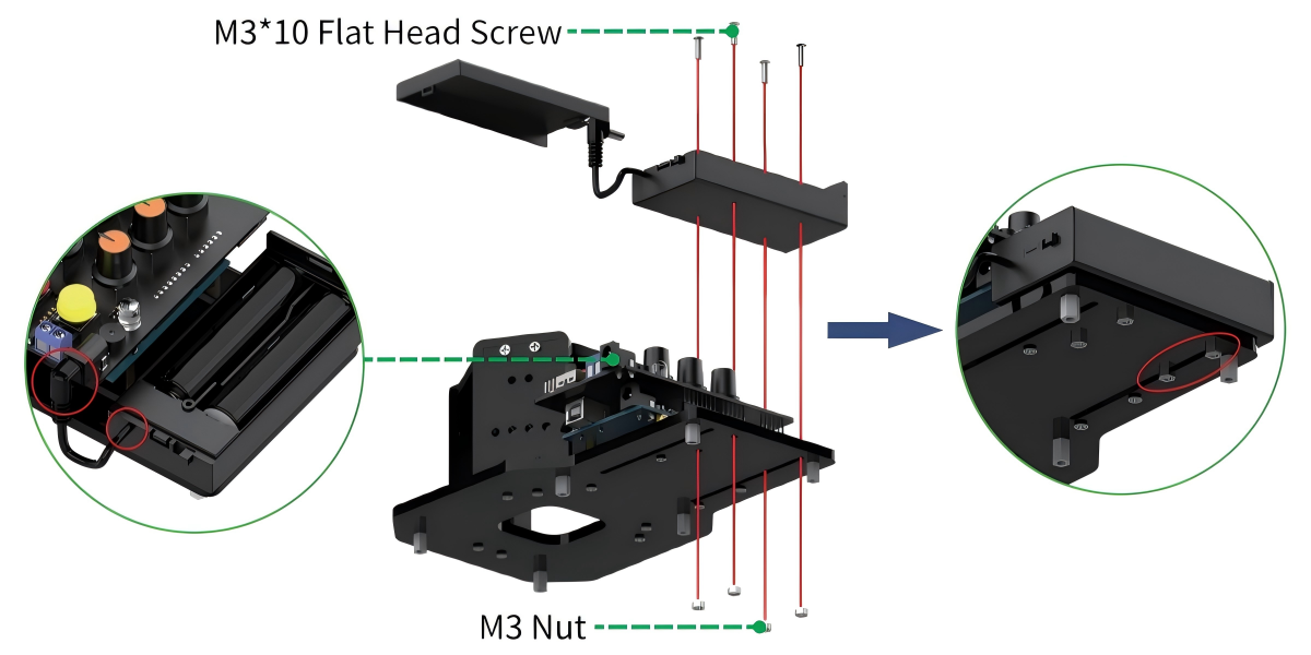
(6) Install battery box to the baseboard with four M3*10 flat head screws and four M3 nuts.
Note
There are two holes are installed in the seam of baseboard.
Ensure that the switch of battery box is turned to “OFF”. Then put the batteries into the battery box and connect the power wire into the DC port of expansion board.
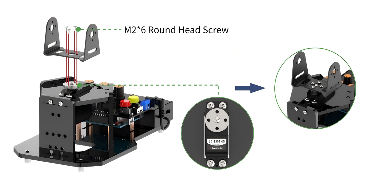
(7) Connect pan-tilt servo to any servo interface, then power on the robotic arm to return to the initial position. White connects to signal wire S, red connects to +, black connects to -. After returning to the neutral position, install U-shaped bracket of baseboard to servo disk with four M2*6 round head screws. Please note that the bottom of the U-shaped bracket should be paralleled to the base during installation.
(8) Connect servo No.4 to any servo interface on the expansion board, and power on the robotic arm to return to the initial position. White connects to signal wire S, middle black connects to +, another black connects to -.
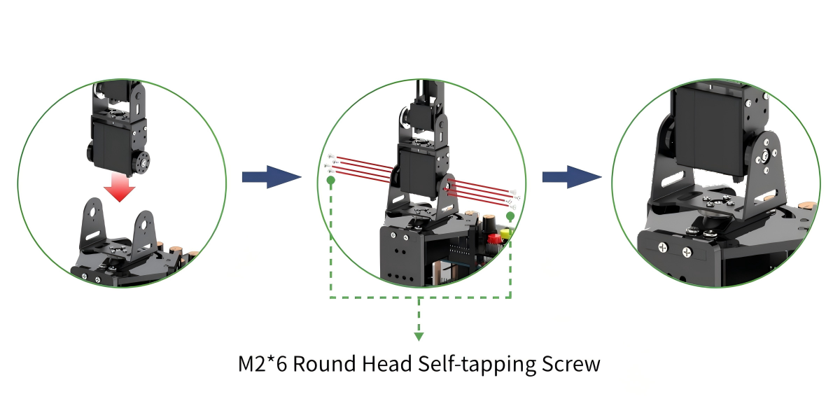
Install the robotic arm to the U-shaped bracket of the baseboard with eight M2*6 round head self-tapping screws.
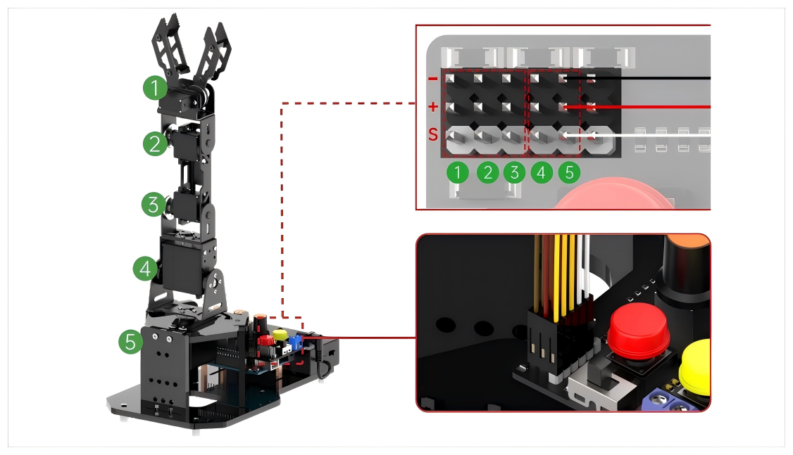
(9) Connect the servo line according to their ID number into the corresponding servo interfaces.
Warning
Do not reverse the positive and negative terminals of the servo. Connectors 1~3: orange connects to signal wire S, red connects to +; connectors 4 and 5: white connects to signal wire S, black\red connects to +, black connect to -.
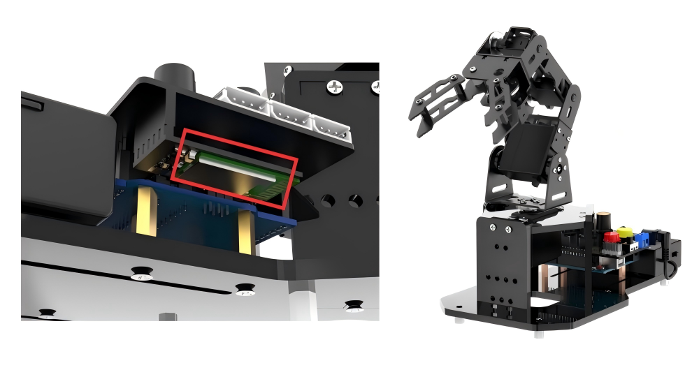
(10) Align the pins of the Bluetooth module with the socket connectors on the expansion board, and connect them into the Bluetooth module interface.
1.4 Charging Instruction
1.4.1 Charging Instruction
(1) Place two 18650 batteries into the battery charger according to positive and negative polarity (positive to positive and negative to negative).
(2) Connect the matching USB cable to the power supply first, then plug it into the USB port of the charger for charging.
Note
You need to prepare a charger head with 5V 3A.
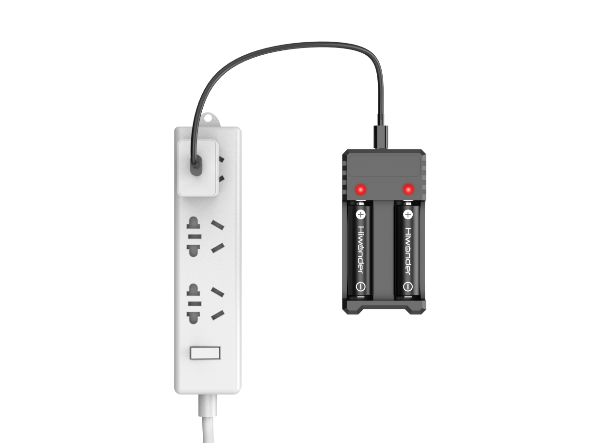
(3) When charging, the indicator light will be red. When the batteries are fully charged, the indicator turns green. Please unplug the charger in time to avoid overcharging.
1.4.2 Battery Usage Guideline
Due to transplantation restrictions, lithium batteries cannot be fully charged during transit. Please fully charge them for your first usage.
(1) Please use the battery charger and USB cable provided with the robot to charge the batteries.
(2) The power indicator will turn red during charging, and it will turn green when the batteries are fully charged. Please disconnect the power supply in time to avoid overcharging the batteries.
(3) If the robotic arm will not be used for an extended period, please fully charge the batteries, switch the battery box to “OFF”, and unplug the power wire of the battery box. Store it in a cool and dry place.
(4) Official Statement: Our company hereby declares that we shall not be held responsible for any damages to the product, financial losses, or safety
accidents caused by failure to comply with the “Precaution and Battery Usage Guideline” of this manual.
1.4.3 Precaution
(1) Please ensure the correct connection of the servo and power wires.
(2) Do not forcefully move the servo after powering on to avoid servo damage.
(3) Do not keep the servo in a limited position for an extended period to avoid servo blocking.
(4) Please ensure that the GPS location and Bluetooth of your phone are turned on when connecting to the app.
(5) Please switch the battery box to “OFF” when connecting the Type-B cable. This action prevents the cable from accidentally touching the power pins on the expansion board, which may cause a short circuit.
(6) Remove the Bluetooth module while downloading the program to avoid program download failure due to serial conflicts.