2. ESP32 Development
2.1 Getting Started
2.1.1 Wiring Instruction
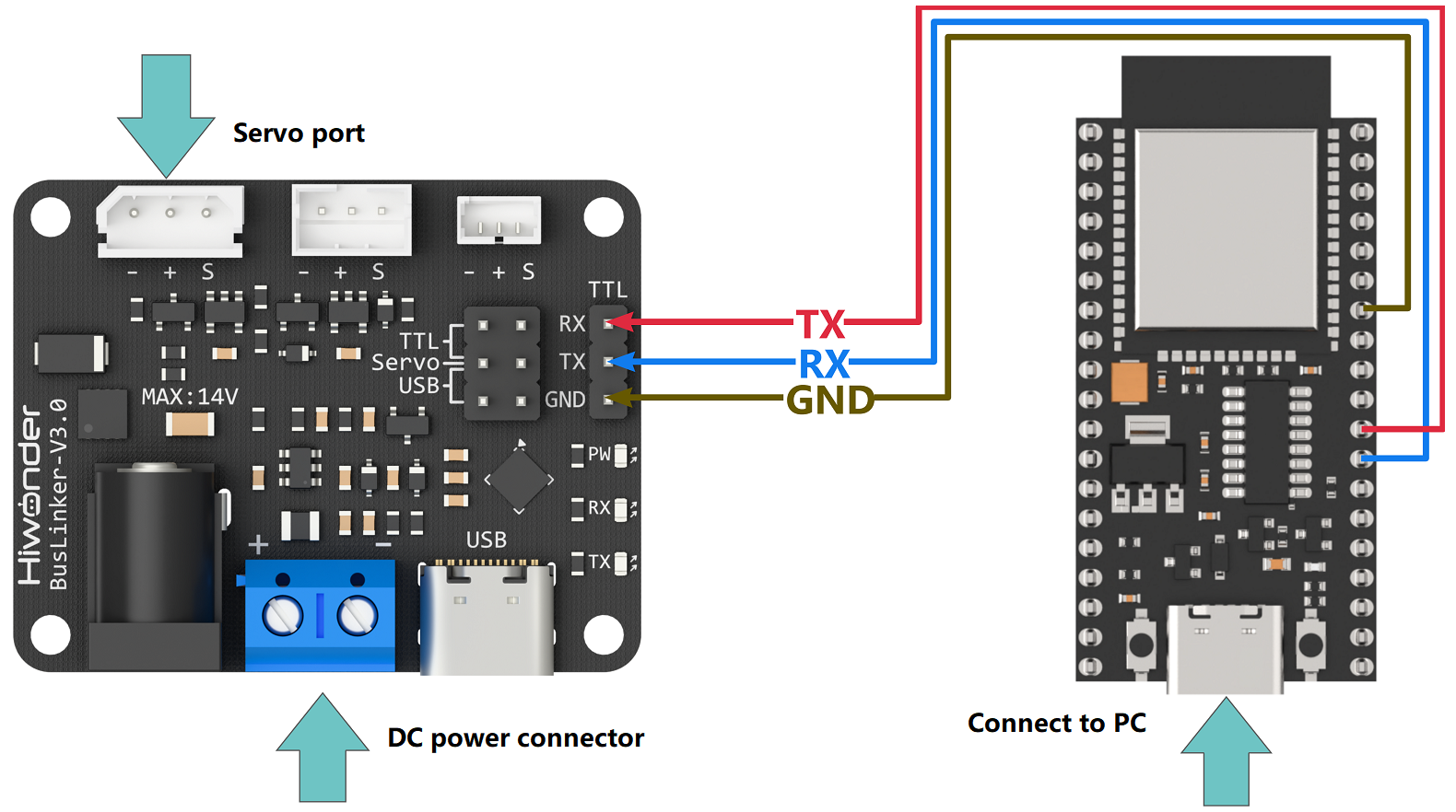
The example in this section uses an ESP32 microcontroller and an ESP32 expansion board for development, with power supplied via a USB cable. The bus servo is connected to the debugging board, which is powered by an 11.1 V lithium battery. The ESP32 microcontroller and the debugging board are then connected through the serial pins using Dupont wires.
Note
When using Hiwonder’s lithium battery, connect the battery cable with the red wire to the positive (+) terminal and the black wire to the negative (–) terminal of the DC port.
Before connecting the battery cables, make sure they are not already attached to the lithium battery. This prevents the risk of a short circuit caused by accidental contact between the positive and negative wires.
2.1.2 Environment Configuration
Install Arduino IDE software on PC. The software package is stored in 2. Softwares -> Arduino Environment Setup. For the detailed operations of Arduino IDE, please refer to the relevant tutorials.
2.2 Development Example
Note
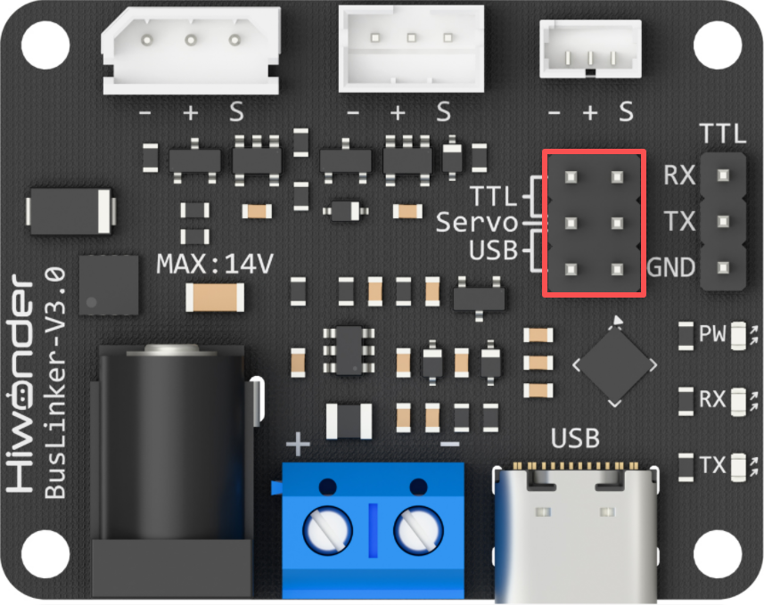
Before running this example, ensure that the jumpers on the debugging board are installed on the Servo and TTL pins. Otherwise, communication will not function properly.
2.2.1 Reading the Servo Status
This example displays the bus servo status information through the debugger window.
2.2.1.1 Run Program
Double-click Serial_Servo.ino located at the ESP Development \ Program folder.
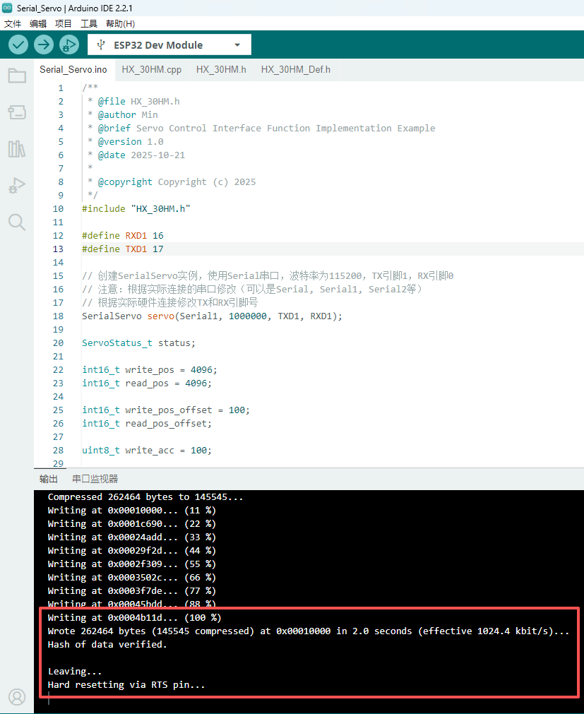
Connect the ESP32 microcontroller to the computer, select the corresponding board type  , and click
  to upload the program.
2.2.1.2 Program Outcome
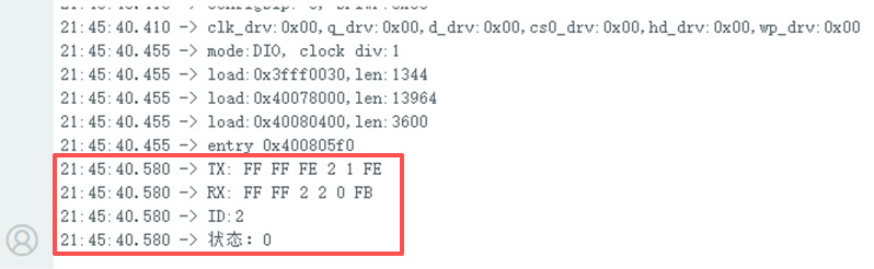
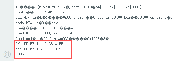
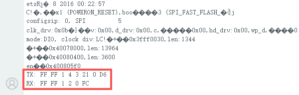
After running the program, the serial debugger prints the sent data packets and the servo status information, which corresponds to the data frames returned by the servo.
2.2.1.3 Program Brief Analysis
Import the servo communication library. Define two hardware serial ports and create a SerialServo instance. Use the Serial port: the baud rate between ESP32 and PC is 115200, and the baud rate with the debugging board is 1000000. TX pin is 1, RX pin is 0.
#include "HX_30HM.h"

#define RXD1 16
#define TXD1 17

SerialServo servo(Serial1, 1000000, TXD1, RXD1);
Note
Modify the serial port according to the actual connection, for example Serial, Serial1, or Serial2, and adjust the TX and RX pin numbers according to the hardware setup.
Define the parameters to send and receive.
ServoStatus_t status;

int16_t write_pos = 4096;
int16_t read_pos = 4096;

int16_t write_pos_offset = 100;
int16_t read_pos_offset;

uint8_t write_acc = 100;

int16_t write_speed = 1000;
int16_t read_speed;

int16_t write_pwm_speed = 1000;

uint16_t write_torque = 1000;

int16_t sync_write1[2][4] = {{1, 0, 1000, 4095},
						   {2, 0, 1000, 4095}};

int16_t sync_write2[2][4] = {{1, 0, 1000, 0},
						   {2, 0, 1000, 0}};
uint8_t read_id[] = {1, 2};
int16_t sync_read_data[2][5];

uint8_t temp;
uint8_t vol;
uint16_t cur;
int16_t read_load;
uint8_t moving_status;
Initialize the main ESP32 serial port for debugging output. The serial debugger prints the sent data packets and the servo-returned data frames. The
pingfunction broadcasts to search for servos, prints the detected ID numbers, and returns the working status of the servo.
void setup() {
  Serial.begin(115200);

  status = servo.ping(0xFE);
  Serial.printf("ID:%d\n", status.id);
  Serial.printf("Status:%X\n", status.error_byte);
}
2.2.2 Reading the Servo Position
This example displays the current position information of the bus servo through the debugger window.
2.2.2.1 Run Program
Double-click Serial_Servo.ino located at the ESP Development \ Program folder.
Connect the ESP32 microcontroller to the computer, select the corresponding board type , and click to upload the program.
2.2.2.2 Program Outcome
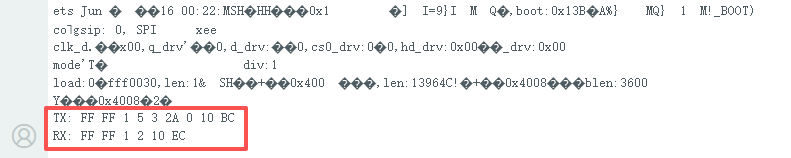
After running the program, the serial debugger prints the sent data packets and the current position of the servo, which corresponds to the data frames returned by the servo.
2.2.2.3 Program Brief Analysis
Import the servo communication library. Define two hardware serial ports and create a SerialServo instance. Use the Serial port: the baud rate between ESP32 and PC is 115200, and the baud rate with the debugging board is 1000000. TX pin is 1, RX pin is 0.
#include "HX_30HM.h"

#define RXD1 16
#define TXD1 17

SerialServo servo(Serial1, 1000000, TXD1, RXD1);
Note
Modify the serial port according to the actual connection, for example Serial, Serial1, or Serial2, and adjust the TX and RX pin numbers according to the hardware setup.
Define the parameters to send and receive.
ServoStatus_t status;

int16_t write_pos = 4096;
int16_t read_pos = 4096;

int16_t write_pos_offset = 100;
int16_t read_pos_offset;

uint8_t write_acc = 100;

int16_t write_speed = 1000;
int16_t read_speed;

int16_t write_pwm_speed = 1000;

uint16_t write_torque = 1000;

int16_t sync_write1[2][4] = {{1, 0, 1000, 4095},
						   {2, 0, 1000, 4095}};

int16_t sync_write2[2][4] = {{1, 0, 1000, 0},
						   {2, 0, 1000, 0}};
uint8_t read_id[] = {1, 2};
int16_t sync_read_data[2][5];

uint8_t temp;
uint8_t vol;
uint16_t cur;
int16_t read_load;
uint8_t moving_status;
Initialize the main ESP32 serial port for debugging output. The serial debugger prints the sent data packets and the servo-returned data frames. The
read_posfunction reads the current position value of servo ID 1 and prints it in the serial debugger.
void setup() {
  Serial.begin(115200);

  status = servo.read_pos(1, &read_pos);
  Serial.println(read_pos);
}
2.2.3 Servo Movement Control in Write Mode
2.2.3.1 Run Program
Double-click Serial_Servo.ino located at the ESP Development \ Program folder.
Connect the ESP32 microcontroller to the computer, select the corresponding board type , and click to upload the program.
2.2.3.2 Program Outcome
After running the program, the serial debugger prints the sent data packets and the data frames returned by the servo. The servo with the specified ID moves to the target position according to the configured parameters.
2.2.3.3 Program Brief Analysis
Import the servo communication library. Define two hardware serial ports and create a SerialServo instance. Use the Serial port: the baud rate between ESP32 and PC is 115200, and the baud rate with the debugging board is 1000000. TX pin is 1, RX pin is 0.
#include "HX_30HM.h"

#define RXD1 16
#define TXD1 17

SerialServo servo(Serial1, 1000000, TXD1, RXD1);
Note
Modify the serial port according to the actual connection, for example Serial, Serial1, or Serial2, and adjust the TX and RX pin numbers according to the hardware setup.
Define the parameters to send and receive.
ServoStatus_t status;

int16_t write_pos = 4096;
int16_t read_pos = 4096;

int16_t write_pos_offset = 100;
int16_t read_pos_offset;

uint8_t write_acc = 100;

int16_t write_speed = 1000;
int16_t read_speed;

int16_t write_pwm_speed = 1000;

uint16_t write_torque = 1000;

int16_t sync_write1[2][4] = {{1, 0, 1000, 4095},
						   {2, 0, 1000, 4095}};

int16_t sync_write2[2][4] = {{1, 0, 1000, 0},
						   {2, 0, 1000, 0}};
uint8_t read_id[] = {1, 2};
int16_t sync_read_data[2][5];

uint8_t temp;
uint8_t vol;
uint16_t cur;
int16_t read_load;
uint8_t moving_status;
Initialize the main ESP32 serial port for debugging output. The serial debugger prints the sent data packets and the servo-returned data frames. The
write_posfunction sets the target position of servo ID 1, and the servo moves to that position.
void setup() {
  Serial.begin(115200);

  status = servo.write_pos(1, write_pos);
}
2.2.4 Servo Movement Control in RegWrite Mode
2.2.4.1 Run Program
Double-click Serial_Servo.ino located at the ESP Development \ Program folder.
Connect the ESP32 microcontroller to the computer, select the corresponding board type , and click to upload the program.
2.2.4.2 Program Outcome
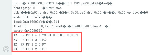
After running the program, the serial debugger prints the sent data packets and the data frames returned by the servo. The servo with the specified ID moves to the target position according to the configured parameters.
2.2.4.3 Program Brief Analysis
Import the servo communication library. Define two hardware serial ports and create a SerialServo instance. Use the Serial port: the baud rate between ESP32 and PC is 115200, and the baud rate with the debugging board is 1000000. TX pin is 1, RX pin is 0.
#include "HX_30HM.h"

#define RXD1 16
#define TXD1 17

SerialServo servo(Serial1, 1000000, TXD1, RXD1);
Note
Modify the serial port according to the actual connection, for example Serial, Serial1, or Serial2, and adjust the > TX and RX pin numbers according to the hardware setup.
Define the parameters to send and receive.
ServoStatus_t status;

int16_t write_pos = 4096;
int16_t read_pos = 4096;

int16_t write_pos_offset = 100;
int16_t read_pos_offset;

uint8_t write_acc = 100;

int16_t write_speed = 1000;
int16_t read_speed;

int16_t write_pwm_speed = 1000;

uint16_t write_torque = 1000;

int16_t sync_write1[2][4] = {{1, 0, 1000, 4095},
						   {2, 0, 1000, 4095}};

int16_t sync_write2[2][4] = {{1, 0, 1000, 0},
						   {2, 0, 1000, 0}};
uint8_t read_id[] = {1, 2};
int16_t sync_read_data[2][5];

uint8_t temp;
uint8_t vol;
uint16_t cur;
int16_t read_load;
uint8_t moving_status;
Initialize the main ESP32 serial port for debugging output. The serial debugger prints the sent data packets and the servo-returned data frames. The
write_reg_pos_exfunction writes the acceleration, speed, and position information to the specified register of servo ID 1 without executing immediately. Execution is deferred and requires calling thereg_actionfunction. After callingreg_action, the servo executes the previously writtenwrite_reg_pos_excommand and moves accordingly.
void setup() {
  Serial.begin(115200);

  status = servo.write_reg_pos_ex(1, write_acc, write_speed, 0);
  status = servo.reg_action(1);
}
2.2.5 Servo Movement Control in SyncWrite Mode
2.2.5.1 Run Program
Double-click Serial_Servo.ino located at the ESP Development \ Program folder.
Connect the ESP32 microcontroller to the computer, select the corresponding board type , and click to upload the program.
2.2.5.2 Program Outcome
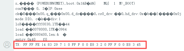
After running the program, the serial debugger prints the sent data packets. The servos with the specified IDs move to the target positions according to the configured parameters.
2.2.5.3 Program Brief Analysis
Import the servo communication library. Define two hardware serial ports and create a SerialServo instance. Use the Serial port: the baud rate between ESP32 and PC is 115200, and the baud rate with the debugging board is 1000000. TX pin is 1, RX pin is 0.
#include "HX_30HM.h"

#define RXD1 16
#define TXD1 17

SerialServo servo(Serial1, 1000000, TXD1, RXD1);
Note
Modify the serial port according to the actual connection, for example Serial, Serial1, or Serial2, and adjust the TX and RX pin numbers according to the hardware setup.
Define the parameters to send and receive.
ServoStatus_t status;

int16_t write_pos = 4096;
int16_t read_pos = 4096;

int16_t write_pos_offset = 100;
int16_t read_pos_offset;

uint8_t write_acc = 100;

int16_t write_speed = 1000;
int16_t read_speed;

int16_t write_pwm_speed = 1000;

uint16_t write_torque = 1000;

int16_t sync_write1[2][4] = {{1, 0, 1000, 4095},
						   {2, 0, 1000, 4095}};

int16_t sync_write2[2][4] = {{1, 0, 1000, 0},
						   {2, 0, 1000, 0}};
uint8_t read_id[] = {1, 2};
int16_t sync_read_data[2][5];

uint8_t temp;
uint8_t vol;
uint16_t cur;
int16_t read_load;
uint8_t moving_status;
The main ESP32 serial port is initialized for debugging output, and the serial debugger prints the sent data packets. The
sync_write_pos_exfunction sets the acceleration, speed, and position information for servo IDs 1 and 2, and the servos move to the specified positions.
void setup() {
  Serial.begin(115200);

  status = servo.sync_write_pos_ex(sync_write1, 2);
}
2.2.6 Setting the Servo Operating Mode
2.2.6.1 Run Program
Double-click Serial_Servo.ino located at the ESP Development \ Program folder.
Connect the ESP32 microcontroller to the computer, select the corresponding board type , and click to upload the program.
2.2.6.2 Program Outcome
After running the program, the serial debugger prints the sent data packets and the data frames returned by the servo. The operating mode of the servo with the specified ID is set.
2.2.6.3 Program Brief Analysis
Import the servo communication library. Define two hardware serial ports and create a SerialServo instance. Use the Serial port: the baud rate between ESP32 and PC is 115200, and the baud rate with the debugging board is 1000000. TX pin is 1, RX pin is 0.
#include "HX_30HM.h"

#define RXD1 16
#define TXD1 17

SerialServo servo(Serial1, 1000000, TXD1, RXD1);
Note
Modify the serial port according to the actual connection, for example Serial, Serial1, or Serial2, and adjust the TX and RX pin numbers according to the hardware setup.
Define the parameters to send and receive.
ServoStatus_t status;

int16_t write_pos = 4096;
int16_t read_pos = 4096;

int16_t write_pos_offset = 100;
int16_t read_pos_offset;

uint8_t write_acc = 100;

int16_t write_speed = 1000;
int16_t read_speed;

int16_t write_pwm_speed = 1000;

uint16_t write_torque = 1000;

int16_t sync_write1[2][4] = {{1, 0, 1000, 4095},
						   {2, 0, 1000, 4095}};

int16_t sync_write2[2][4] = {{1, 0, 1000, 0},
						   {2, 0, 1000, 0}};
uint8_t read_id[] = {1, 2};
int16_t sync_read_data[2][5];

uint8_t temp;
uint8_t vol;
uint16_t cur;
int16_t read_load;
uint8_t moving_status;
Initialize the main ESP32 serial port for debugging output. The serial debugger prints the sent data packets and the servo-returned data frames. The
select_modefunction sets the operating mode of servo ID 1.
void setup() {
  Serial.begin(115200);

  status = servo.select_mode(1, 0);
}