4. STM32 Communication
4.1 IIC Communication Instruction
4.1.1 Getting Started
Wiring Instruction
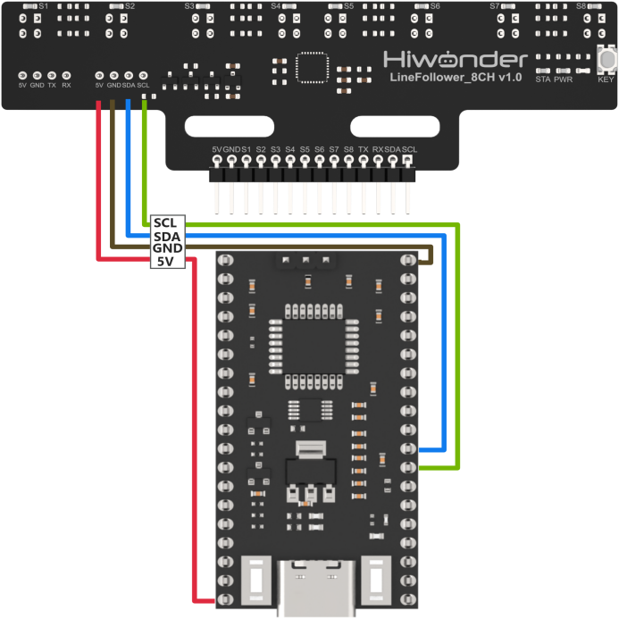
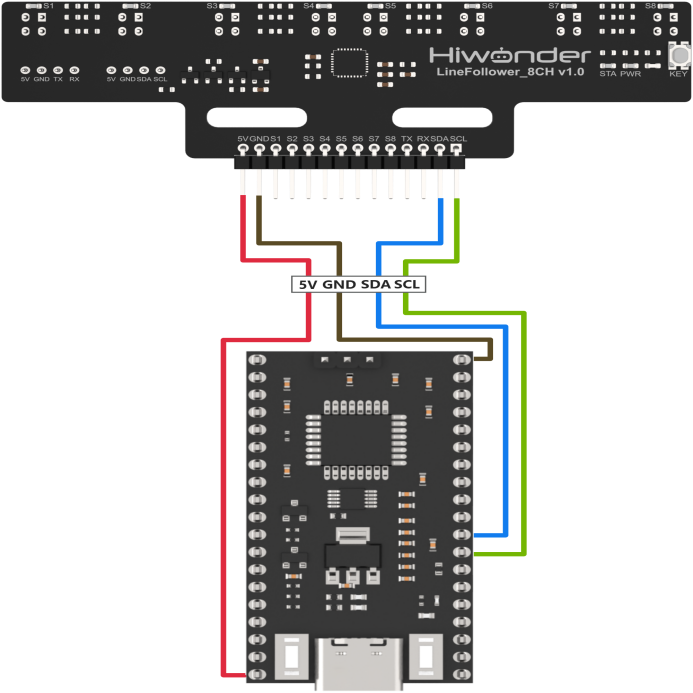
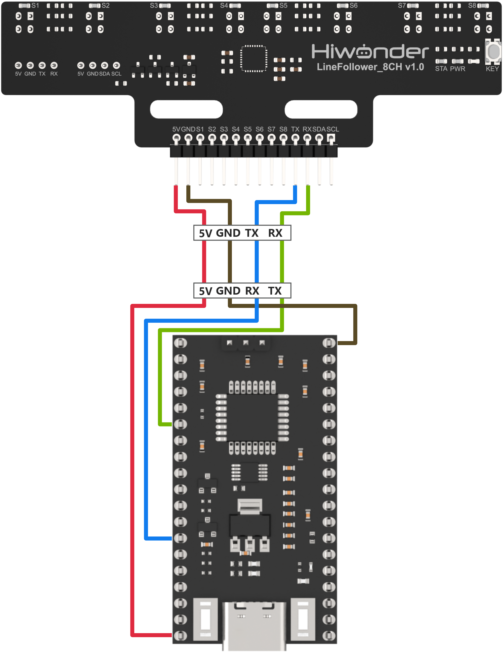
Connect the 5V, GND, SDA, and SCL pins of the 8-ch Line Follower to the corresponding pins on the STM32 controller. The wiring method is shown in the diagram below:
Note
Before powering on, ensure that no metal objects are touching the controller. Otherwise, the exposed pins at the bottom of the board may cause a short circuit and damage the controller.
Program Download
(1) Connect the controller to the computer using a USB cable.
(2) Double-click to open the STM32 serial programming software FlyMcu.

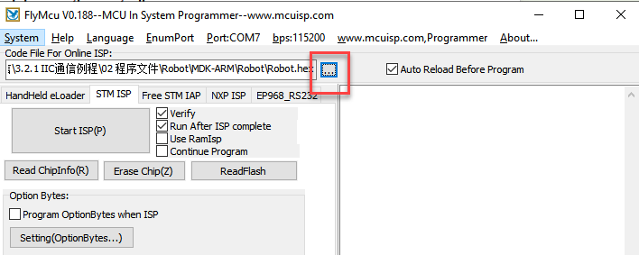
(3) Click the “…” icon and select the HEX file to be programmed from the path: Robot\MDK-ARM\Robot.

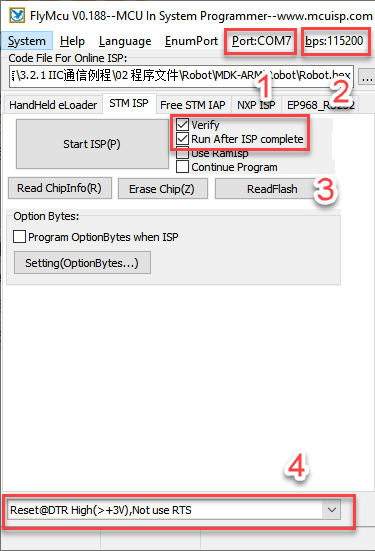
(4) In position ①, select the corresponding serial port number for the controller. In position ②, set the baud rate to 115200. In positions ③ and ④, configure the options as shown in the image.

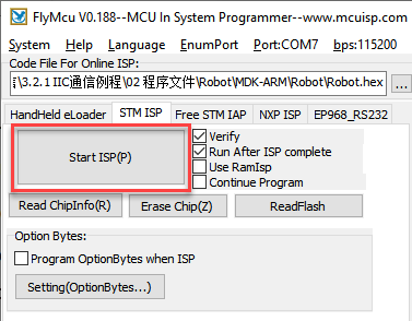
(5) Click “Start ISP(P)”, then press the RST button on the controller. The program will automatically begin downloading. Once the following content appears in the log output on the right, the program download will be complete.
4.1.2 Test Case
Project Outcome
Note
Before recognition, you need to perform the one-click intelligent calibration for the sensor to ensure proper detection.
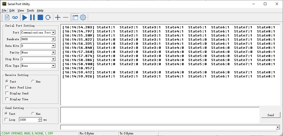
Once the 8-ch Line Follower detects the corresponding color of the line-following target, the serial port will print the status, analog values, and threshold values of each sensor. The printed data will appear as follows:
Program Brief Analysis
(1) First, the program-related libraries and the line-following sensor library need to be imported. The line-following sensor library contains the functional interfaces for the sensor.
18 19 20 21 22 23 24 25 26 27 28 29 30 31 32 33 34 35 36 37 38 | /* Includes ------------------------------------------------------------------*/ #include "main.h" #include "adc.h" #include "dma.h" #include "i2c.h" #include "spi.h" #include "tim.h" #include "usart.h" #include "gpio.h" /* Private includes ----------------------------------------------------------*/ /* USER CODE BEGIN Includes */ #include "global.h" #include "stdio.h" #include "stdlib.h" #include "led.h" #include "buzzer.h" #include "adc_sample.h" #include "LineFollow.h" /* USER CODE END Includes */ |
(2) In the main function, the relevant hardware is initialized, and the LineFollowIIC_init() function is called to initialize the line-following sensor in manual transmission mode. In this mode, the main controller must send a read command to the sensor to obtain the corresponding data.
92 93 94 95 96 97 98 99 100 101 102 103 104 105 106 107 108 109 110 111 112 113 114 115 116 117 118 119 120 121 122 123 | /* Reset of all peripherals, Initializes the Flash interface and the Systick. */ HAL_Init(); /* USER CODE BEGIN Init */ /* USER CODE END Init */ /* Configure the system clock */ SystemClock_Config(); /* USER CODE BEGIN SysInit */ __HAL_RCC_I2C1_CLK_ENABLE(); __HAL_RCC_DMA1_CLK_ENABLE(); /* USER CODE END SysInit */ /* Initialize all configured peripherals */ MX_GPIO_Init(); MX_DMA_Init(); MX_TIM3_Init(); MX_USART3_UART_Init(); MX_SPI1_Init(); MX_USART1_UART_Init(); MX_ADC1_Init(); MX_I2C1_Init(); MX_TIM4_Init(); MX_USART2_UART_Init(); /* Initialize interrupts */ MX_NVIC_Init(); /* USER CODE BEGIN 2 */ led_init(); LineFollowIIC_init(); |
(3) In the sensor’s initialization function, calling this function will interact with the sensor’s address through LineFollow.write_data(), LineFollow.read_data(), and LineFollow.dev_addr.
59 60 61 62 63 64 65 | void LineFollowIIC_init() { memset(&LineFollow, 0, sizeof(LineFollow)); LineFollow.write_data = write_data; LineFollow.read_data = read_data; LineFollow.dev_addr = LineFollow_ADDRESS; } |
(4) In the while loop, to get the sensor’s level value, for example, the LineFollowIIC_State() function is used to obtain the level status of the four line-following sensors, and the results are stored in the LineFollowLearn object. The data is then printed out via the serial port.
129 130 131 132 133 134 135 136 137 138 139 140 141 142 143 144 145 146 147 148 149 150 151 152 153 154 155 | while (1) { /* USER CODE END WHILE */ /* USER CODE BEGIN 3 */ /* Read State */ LineFollowIIC_State(&LineFollowLearn); printf("State1:%d State2:%d State3:%d State4:%d State5:%d State6:%d State7:%d State8:%d\r\n", LineFollowLearn.data[0], LineFollowLearn.data[1], LineFollowLearn.data[2], LineFollowLearn.data[3], LineFollowLearn.data[4], LineFollowLearn.data[5], LineFollowLearn.data[6], LineFollowLearn.data[7]); /* Read Analog */ LineFollowIIC_Analog(&LineFollowLearn); printf("Analog1:%d Analog2:%d Analog3:%d Analog4:%d Analog5:%d Analog6:%d Analog7:%d Analog8:%d\r\n", LineFollowLearn.data[0], LineFollowLearn.data[1], LineFollowLearn.data[2], LineFollowLearn.data[3], LineFollowLearn.data[4], LineFollowLearn.data[5], LineFollowLearn.data[6], LineFollowLearn.data[7]); /* Read Threshold */ LineFollowIIC_Threshold(&LineFollowLearn); printf("Threshold1:%d Threshold2:%d Threshold3:%d Threshold4:%d Threshold5:%d Threshold6:%d Threshold7:%d Threshold8:%d\r\n", LineFollowLearn.data[0], LineFollowLearn.data[1], LineFollowLearn.data[2], LineFollowLearn.data[3], LineFollowLearn.data[4], LineFollowLearn.data[5], LineFollowLearn.data[6], LineFollowLearn.data[7]); HAL_Delay(400); } /* USER CODE END 3 */ } |
(5) In the implementation of LineFollowIIC_State(), the data type is first checked, and the HAL_I2C_STATE_READY() function is used to acquire the I2C data. Finally, a for loop is used to parse the data, and the level data of each sensing unit is obtained.
67 68 69 70 71 72 73 74 75 76 77 78 | bool LineFollowIIC_State(LineFollowHandleTypeDef* State) { if(receive_from_device(&LineFollow, LineFollow_STATE_REG, LineFollow.results, 1)) { while(HAL_I2C_STATE_READY != HAL_I2C_GetState(&hi2c1)); for(int i=0; i<sizeof(LineFollow.data);i++){ State->data[i] = (LineFollow.results[0] >> i) & 0x01; } return true; } return false; } |
4.2 UART Communication Instruction
4.2.1 Preparation
Wiring Instruction
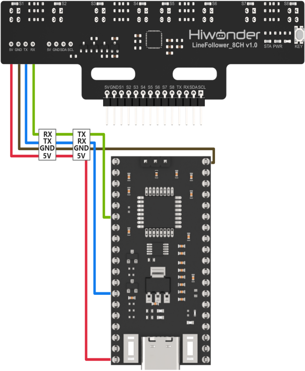
Connect the 5V, GND, TX, and RX pins of the 8-ch Line Follower to the corresponding pins on the STM32 controller. The wiring method is shown in the diagram below:
Note
Before powering on, ensure that no metal objects are touching the controller. Otherwise, the exposed pins at the bottom of the board may cause a short circuit and damage the controller.
Program Download
(1) Connect the controller to the computer using a USB cable.
(2) Double-click to open the STM32 serial programming software FlyMcu. 
(3) Click the “…” icon and select the HEX file to be programmed from the path: Robot\MDK-ARM\Robot.
(4) In position ①, select the corresponding serial port number for the controller. In position ②, set the baud rate to 115200. In positions ③ and ④, configure the options as shown in the image.
(5) Click “Start ISP(P)”, then press the RST button on the controller. The program will automatically begin downloading. Once the following content appears in the log output on the right, the program download will be complete.
4.4.2 Test Case
Project Outcome
Note
Before recognition, you need to perform the one-click intelligent calibration for the sensor to ensure proper detection.
When the 8-channel line follower detects a line of the corresponding color, the status of each sensor channel will be printed via the serial port. The program allows switching between displaying analog values and threshold values.

Program Brief Analysis
(1) First, the program-related libraries and the line-following sensor library need to be imported. The line-following sensor library contains the functional interfaces for the sensor.
18 19 20 21 22 23 24 25 26 27 28 29 30 31 32 33 34 35 36 37 38 | /* Includes ------------------------------------------------------------------*/ #include "main.h" #include "adc.h" #include "dma.h" #include "i2c.h" #include "spi.h" #include "tim.h" #include "usart.h" #include "gpio.h" /* Private includes ----------------------------------------------------------*/ /* USER CODE BEGIN Includes */ #include "global.h" #include "stdio.h" #include "stdlib.h" #include "led.h" #include "buzzer.h" #include "adc_sample.h" #include "LineFollow.h" /* USER CODE END Includes */ |
(2) In the main function, the relevant hardware is initialized, and the LineFollowUART_init() function is called to initialize the line-following sensor in manual transmission mode. In this mode, the main controller must send a read command to the sensor to obtain the corresponding data.
94 95 96 97 98 99 100 101 102 103 104 105 106 107 108 109 110 111 112 113 114 115 116 117 118 119 120 121 122 123 124 | HAL_Init(); /* USER CODE BEGIN Init */ /* USER CODE END Init */ /* Configure the system clock */ SystemClock_Config(); /* USER CODE BEGIN SysInit */ __HAL_RCC_I2C1_CLK_ENABLE(); __HAL_RCC_DMA1_CLK_ENABLE(); /* USER CODE END SysInit */ /* Initialize all configured peripherals */ MX_GPIO_Init(); MX_DMA_Init(); MX_TIM3_Init(); MX_USART3_UART_Init(); MX_SPI1_Init(); MX_USART1_UART_Init(); MX_ADC1_Init(); MX_I2C1_Init(); MX_TIM4_Init(); MX_USART2_UART_Init(); /* Initialize interrupts */ MX_NVIC_Init(); /* USER CODE BEGIN 2 */ led_init(); LineFollowUART_init(LINEFOLLOW_MODE_MANUAL); |
(3) In the sensor initialization function, the LineFollow_write_and_read() function is used to send a command to set the working mode of the sensor. Important: The sensor only accepts this working mode command once after power-up. If you want to switch modes, you must power cycle the sensor and then send the command again.
155 156 157 158 159 160 161 162 163 164 | void LineFollowUART_init(uint8_t Mode) { memset(&LineFollow, 0, sizeof(LineFollow)); __HAL_UART_CLEAR_FLAG(&huart2, UART_FLAG_TXE); __HAL_UART_CLEAR_FLAG(&huart2, UART_FLAG_TC); __HAL_UART_CLEAR_FLAG(&huart2, UART_FLAG_RXNE); LineFollow.work_mode = Mode; LineFollow_write_and_read(&LineFollow, LineFollow.work_mode, true); LineFollow.it_state = LINEFOLLOW_WRITE_DATA_READY; } |
(4) In the while loop, to get the sensor’s level value, for example, the LineFollowUART_State() function is used to obtain the level status of the four line-following sensors, and the results are stored in the LineFollowLearn object. The data is then printed out via the serial port. Because the working mode in UART mode can only be changed by power cycling, it is not possible to print digital values, analog values, and threshold values at the same time.
130 131 132 133 134 135 136 137 138 139 140 141 142 143 144 145 146 147 148 149 150 151 152 153 154 155 156 | while (1) { /* USER CODE END WHILE */ /* USER CODE BEGIN 3 */ /* Read State */ LineFollowUART_State(&LineFollowLearn); printf("State1:%d State2:%d State3:%d State4:%d State5:%d State6:%d State7:%d State8:%d\r\n", LineFollowLearn.data[0], LineFollowLearn.data[1], LineFollowLearn.data[2], LineFollowLearn.data[3], LineFollowLearn.data[4], LineFollowLearn.data[5], LineFollowLearn.data[6], LineFollowLearn.data[7]); /* Read Analog */ // LineFollowUART_Analog(&LineFollowLearn); // printf("Analog1:%d Analog2:%d Analog3:%d Analog4:%d Analog5:%d Analog6:%d Analog7:%d Analog8:%d\r\n", // LineFollowLearn.data[0], LineFollowLearn.data[1], LineFollowLearn.data[2], LineFollowLearn.data[3], // LineFollowLearn.data[4], LineFollowLearn.data[5], LineFollowLearn.data[6], LineFollowLearn.data[7]); /* Read Threshold */ // LineFollowUART_Threshold(&LineFollowLearn); // printf("Threshold1:%d Threshold2:%d Threshold3:%d Threshold4:%d Threshold5:%d Threshold6:%d Threshold7:%d Threshold8:%d\r\n", // LineFollowLearn.data[0], LineFollowLearn.data[1], LineFollowLearn.data[2], LineFollowLearn.data[3], // LineFollowLearn.data[4], LineFollowLearn.data[5], LineFollowLearn.data[6], LineFollowLearn.data[7]); HAL_Delay(400); } /* USER CODE END 3 */ } |
(5) In the implementation of LineFollowUART_State(), the working mode is first checked. If the mode is manual transmission, LineFollow_write_and_read() is used to send the LINEFOLLOW_MODE_MANUAL_STATE command to request digital state data from the sensor. According to the protocol, the returned data is 1 byte. A for loop is then used to parse each bit, allowing the digital state of each probe to be obtained.
166 167 168 169 170 171 172 173 174 175 176 177 178 179 180 | bool LineFollowUART_State(LineFollowHandleTypeDef* State) { if(LineFollow.work_mode == LINEFOLLOW_MODE_MANUAL) { LineFollow.manual_mode = LINEFOLLOW_MODE_MANUAL_STATE; if (0 == LineFollow_write_and_read(&LineFollow, LINEFOLLOW_MODE_MANUAL_STATE, false)) { for(int i=0; i<sizeof(LineFollow.data);i++){ State->data[i] = (LineFollow.results[0] >> i) & 0x01; } LineFollow.it_state = LINEFOLLOW_WRITE_DATA_READY; return true; } } |
(6) If the mode is automatic transmission, no command needs to be sent manually. Instead, LINEFOLLOW_CMD_NULL is used as the argument, indicating that no data is sent to the sensor. When the sensor returns data, a loop is used to parse it.
180 181 182 183 184 185 186 187 188 189 190 191 192 193 194 | else { if (0 == LineFollow_write_and_read(&LineFollow, LINEFOLLOW_CMD_NULL, false)) { for(int i=0; i<sizeof(LineFollow.data);i++){ State->data[i] = (LineFollow.results[0] >> i) & 0x01; } LineFollow.it_state = LINEFOLLOW_WRITE_DATA_READY; return false; } } return false; } |
(7) In the LineFollowUART_Analog() function, the data from the sensor is sent in data frame format. According to the UART protocol, each frame contains a frame header, command, data length, data, and checksum. Once a frame is received, the LineFollow_rx_handler() function verifies and processes the data. The parsed analog values are then stored in LineFollow.results. A for loop separates the high and low 8 bits of each data point and combines them to reconstruct the full analog values.
195 196 197 198 199 200 201 202 203 204 205 206 207 208 209 210 211 212 213 214 215 216 217 218 219 220 221 222 223 224 225 | bool LineFollowUART_Analog(LineFollowHandleTypeDef* Analog) { uint8_t count = 0; if(LineFollow.work_mode == LINEFOLLOW_MODE_MANUAL) { LineFollow.manual_mode = LINEFOLLOW_MODE_MANUAL_ANALOG; if (0 == LineFollow_write_and_read(&LineFollow, LINEFOLLOW_MODE_MANUAL_ANALOG, false)) { for(int i=0; i<sizeof(LineFollow.data);i++){ Analog->data[i] = LineFollow.results[count] | (LineFollow.results[count+1] << 8); count += 2; } LineFollow.it_state = LINEFOLLOW_WRITE_DATA_READY; return true; } } else { if (0 == LineFollow_write_and_read(&LineFollow, LINEFOLLOW_CMD_NULL, false)) { for(int i=0; i<sizeof(LineFollow.data);i++){ Analog->data[i] = LineFollow.results[count] | (LineFollow.results[count+1] << 8); count += 2; } LineFollow.it_state = LINEFOLLOW_WRITE_DATA_READY; return true; } } return false; } |
(8) The LineFollowUART_Threshold() function follows the same reception and parsing process as LineFollowUART_Analog(), except that the returned data represents threshold values instead of analog ones.
227 228 229 230 231 232 233 234 235 236 237 238 239 240 241 242 243 244 245 246 247 248 249 250 251 252 253 254 255 256 257 | bool LineFollowUART_Threshold(LineFollowHandleTypeDef* Threshold) { uint8_t count = 0; if(LineFollow.work_mode == LINEFOLLOW_MODE_MANUAL) { LineFollow.manual_mode = LINEFOLLOW_MODE_MANUAL_THRESHOLD; if (0 == LineFollow_write_and_read(&LineFollow, LINEFOLLOW_MODE_MANUAL_THRESHOLD, false)) { for(int i=0; i<sizeof(LineFollow.data);i++){ Threshold->data[i] = LineFollow.results[count] | (LineFollow.results[count+1] << 8); count += 2; } LineFollow.it_state = LINEFOLLOW_WRITE_DATA_READY; return true; } } else { if (0 == LineFollow_write_and_read(&LineFollow, LINEFOLLOW_CMD_NULL, false)) { for(int i=0; i<sizeof(LineFollow.data);i++){ Threshold->data[i] = LineFollow.results[count] | (LineFollow.results[count+1] << 8); count += 2; } LineFollow.it_state = LINEFOLLOW_WRITE_DATA_READY; return true; } } return false; } |