3. Arduino Communication
3.1 IIC Communication Instruction
3.1.1 Getting Started
Wiring Instruction
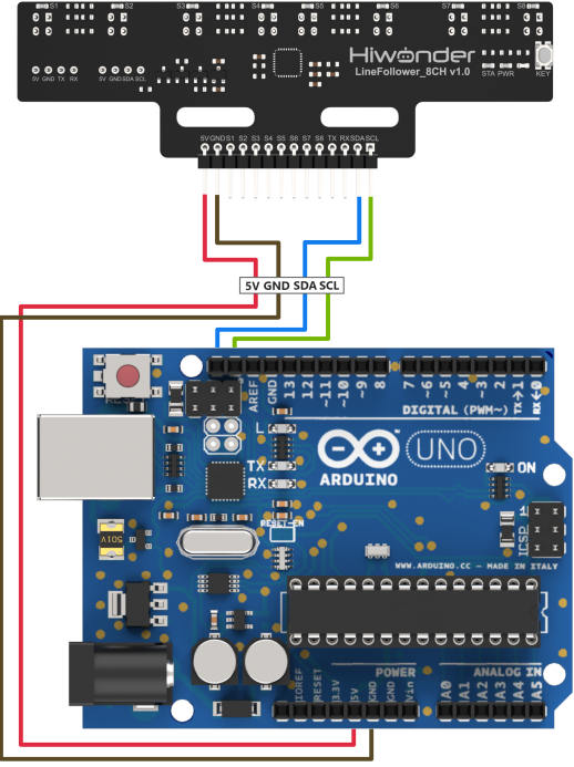
(1) Connect the 5V, GND, SDA, and SCL pins of the 8-ch Line Follower to the corresponding pins on the Arduino controller. The wiring method is shown in the diagram below:

Note
Before powering on, ensure that no metal objects are touching the controller. Otherwise, the exposed pins at the bottom of the board may cause a short circuit and damage the controller.
Program Download
(1) Connect the Arduino controller to the computer via USB cable.
(2) Open the program file located in the same directory as this document: Program\LineFollowerLearn8CH_I2C_Test
(3) Select “Arduino UNO” as the development board and choose the correct port number.
(4) Then click the button  to upload the program to the Arduino and wait for it to complete.
3.1.2 Test Case
Project Outcome
Note
Before recognition, you need to perform the one-click intelligent calibration for the sensor to ensure proper detection.
(1) Once the 8-ch Line Follower detects the corresponding color of the line-following target, the serial port will print the status, analog values, and threshold values of each sensor. The printed data will appear as follows:
Program Brief Analysis
(1) The Wire.h library is imported, which contains the I2C communication class.
1 | #include "Wire.h" |
(2) The macro definitions specify the input/output pins for UART, define the number of channels for the 8-ch Line Follower to 8 channels, and specify the sensor’s register addresses.
1 2 3 4 5 6 7 8 9 | #include "Wire.h" #define SENSOR_SUM 8 //Number of sensor channels (传感器通道数) #define I2C_ADDR 0x5D //Sensor I2C address (传感器I2C地址) #define SensorStateReg (5u) //Address of sensor channel state data register (传感器全通道状态数据寄存器地址) #define SensorAnalogReg (6u) //Address of channel 1 analog value register (low 8 bits) (传感器通道1模拟值寄存器低8位地址) #define SensorThresholdReg (22u) //Address of channel 1 threshold register (low 8 bits) (传感器通道1阈值寄存器低8位地址) |
(3) In the setup function, the serial baud rate is initialized to 115200, and Wire.begin() is called to initialize IIC communication.
11 12 13 14 15 | void setup() { Serial.begin(115200); //Initialize serial communication (初始化串口) Wire.begin(); //Initialize I2C (初始化I2C) } |
(4) In the loop function, Wire.beginTransmission() is used to specify the device address, and Wire.write() is used to send the SensorStateReg (status register) address to the device. Then, Wire.requestFrom() is called to send a request to read 1 byte of data. Wire.readBytes() is used to read the data and store it in the temp array. A for loop is used to parse the state data for each sensor channel, and the results are printed via the serial port.
17 18 19 20 21 22 23 24 25 26 27 28 29 30 31 32 33 34 35 | void loop() { uint8_t temp[SENSOR_SUM*2] = {0}; uint16_t data[SENSOR_SUM] = {0}; Wire.beginTransmission(I2C_ADDR); //Start communication (开始通信) Wire.write(SensorStateReg); //Send the address of the state data register (发送状态数据寄存器地址) Wire.endTransmission(); Wire.requestFrom(I2C_ADDR, 1); //Send read request for 1 byte of data (发送读请求,请求1Byte数据) Wire.readBytes(temp, 1); //Read 1 byte of data into temp (读取1Byte数据,保存到temp) for(uint8_t len = 0; len < SENSOR_SUM; len++) { data[len]= ((temp[0] >> len) & 0x01); //Parse data and extract state value of each channel (解析数据,提取各通道状态值) Serial.print(" State");Serial.print(len+1);Serial.print(":");Serial.print(data[len]);// Print state of each sensor channel via serial (串口打印传感器各通道状态) } Serial.println(); Wire.endTransmission(); //End communication (结束通信) delay(10); |
(5) Next, Wire.write(SensorAnalogReg) is used to send the analog value register address. Then, Wire.requestFrom() is called to request 8 * 2 bytes of data, the data from all 8 channels. Wire.readBytes() is used to read the 8 * 2 bytes of data and store them in temp. Finally, a for loop is used to parse the analog values for each channel and print the results via the serial port.
38 39 40 41 42 43 44 45 46 47 48 49 50 51 52 53 54 | // Wire.beginTransmission(I2C_ADDR); //Start communication (开始通信) Wire.write(SensorAnalogReg); //Send the address of the analog value register (发送模拟值寄存器地址) Wire.endTransmission(); Wire.requestFrom(I2C_ADDR, SENSOR_SUM*2); //Send read request for 8*2 bytes of data (发送读请求,请求8*2 Byte数据,请求8个通道的全部数据) Wire.readBytes(temp, SENSOR_SUM*2); //Read 8*2 bytes of data into temp (读取8*2 Byte数据,保存到temp,读取8个通道的全部数据) Wire.endTransmission(); //End communication (结束通信) uint8_t count = 0; for(uint8_t len = 0; len < SENSOR_SUM; len++) { data[len]= (temp[count]) | (temp[count+1]<<8); //Parse data by combining low and high 8-bit analog values into 16-bit (解析数据,把各通道模拟值低8位和高8位数据合并为16位数据) Serial.print(" Analog");Serial.print(len+1);Serial.print(":");Serial.print(data[len]);//Print analog value of each sensor channel via serial (串口打印传感器各通道模拟值) count += 2; } Serial.println(); delay(10); |
(6) Then, Wire.beginTransmission() is used again to specify the device address, and Wire.write() sends the threshold register address. Wire.requestFrom() is called to request 8 * 2 bytes of data, reading all data from the 8 channels. Finally, Wire.readBytes() is used to read the data and store it in temp. A for loop is used to parse the threshold data for each sensor channel and print the results via the serial port.
56 57 58 59 60 61 62 63 64 65 66 67 68 69 70 71 72 73 74 | Wire.beginTransmission(I2C_ADDR); //Start communication (开始通信) Wire.write(SensorThresholdReg); //Send the address of the threshold register (发送阈值寄存器地址) Wire.endTransmission(); Wire.requestFrom(I2C_ADDR, SENSOR_SUM*2); //Send read request for 8*2 bytes of data (发送读请求,请求8*2 Byte数据,请求8个通道的全部数据) Wire.readBytes(temp, SENSOR_SUM*2); //Read 8*2 bytes of data into temp (读取8*2 Byte数据,保存到temp,读取8个通道的全部数据) Wire.endTransmission(); //End communication (结束通信) count = 0; for(uint8_t len = 0; len < SENSOR_SUM; len++) { data[len]= (temp[count]) | (temp[count+1]<<8); //Parse data by combining low and high 8-bit threshold values into 16-bit (解析数据,把各通道阈值低8位和高8位数据合并为16位数据) Serial.print(" Thres");Serial.print(len+1);Serial.print(":");Serial.print(data[len]);//Print threshold value of each sensor channel via serial (串口打印传感器各通道阈值) count += 2; } Serial.println(); delay(50); } |
3.2 UART Communication Instruction
3.2.1 Preparation
Wiring Instruction
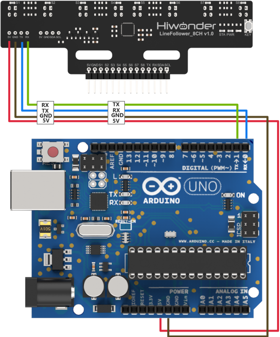
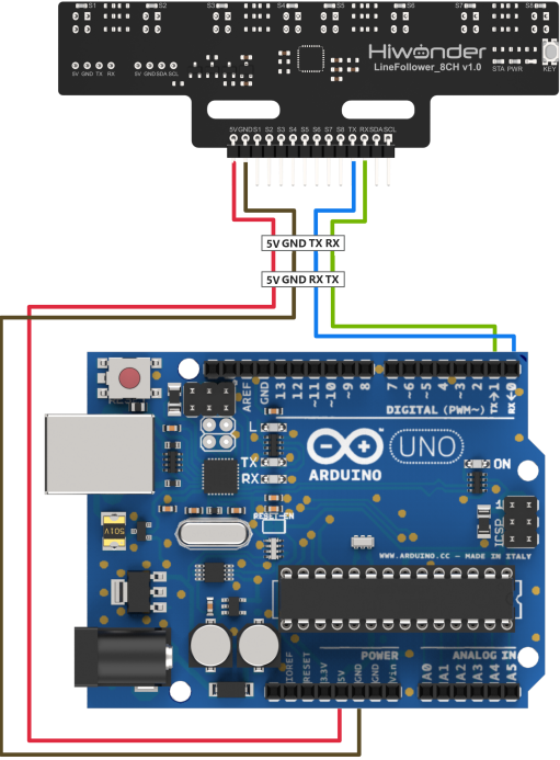
(1) Connect the 5V, GND, TX, and RX pins of the 8-ch Line Follower to the corresponding pins on the ESP controller. The wiring method is shown in the diagram below:
Note
Before powering on, ensure that no metal objects are touching the controller. Otherwise, the exposed pins at the bottom of the board may cause a short circuit and damage the controller.
Program Download
(1) Connect the ESP32 controller to your computer using a USB cable.
(2) Open the program file located in the same directory as this document: Program\LineFollowerLearn8CH_I2C_Test
(3) Select “ESP32 Dev Module” as the development board and choose the correct port number.
(4) Then click the button  to upload the program to the ESP controller and wait for it to complete.
3.2.2 Test Case
Project Outcome
Note
Before recognition, you need to perform the one-click intelligent calibration for the sensor to ensure proper detection.
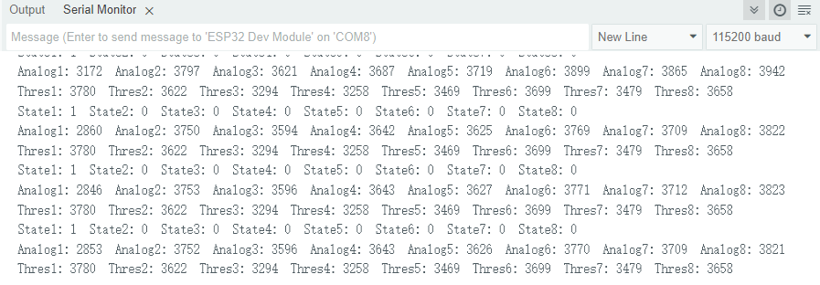
(1) Once the 8-ch Line Follower detects the corresponding color of the line-following target, the serial port will print the status, analog values, and threshold values of each sensor. The printed data will appear as follows:

Program Brief Analysis
(1) Macro definitions are used to specify the UART data input and output pins, define the number of channels for the 8-ch sensor as 8, and define the communication serial port as UART 1.
2 3 4 5 6 7 8 | // Define UART pins (定义UART引脚) #define UART_RX 4 #define UART_TX 5 #define SENSOR_SUM 8 //Number of sensor channels (传感器通道数) HardwareSerial UART(1); //Define the serial port for module communication (定义模块通信串口) |
(2) In the setup function, the serial baud rate is initialized to 115200, and UART.setPins() is used to set the communication pins, followed by UART.begin() to initialize the communication serial port. Next, the program uses UART.write() to send a mode command, which sets the sensor to manual mode.
26 27 28 29 30 31 32 33 34 | void setup() { Serial.begin(115200); //Initialize debug serial port (初始化调试串口) UART.setPins(UART_RX, UART_TX); //Set UART pin configuration (设置通信串口引脚) UART.begin(115200, SERIAL_8N1); //Initialize communication UART (初始化通信串口) Serial.println("Start test..."); UART.write(0); // Set to manual mode. 0: manual mode, 1: auto send state, 2: auto send analog, 3: auto send threshold (设置手动模式。0:手动模式,1:自动发送状态数据,2:自动发送模拟值,3:自动发送阈值) } |
(3) A WriteLock flag is defined to introduce a state lock for controlling the serial read/write status. If the write lock state is 0, the read-level status command is sent. Otherwise, the received data is saved, parsed, and printed out.
37 38 39 40 41 42 43 44 45 46 47 48 49 50 51 52 53 54 55 56 57 58 | uint8_t WriteLock = 0; void loop() { uint16_t data[SENSOR_SUM] = {0}; uint8_t temp[SENSOR_SUM*2+5] = {0}; if(UART.availableForWrite() && 0 == WriteLock) //Check if writable and if write lock is cleared (检测可写状态和写入锁状态) { UART.write(1); // Send command to read state (发送读取状态指令) WriteLock = 1; } if(UART.available() && 1 == WriteLock) //Check if data is available and if write lock is set (检测可读状态和写入锁状态) { UART.readBytes(temp, 1); //Read 1 byte of data into temp (读取1Byte数据,保存到temp) for(uint8_t len = 0; len < SENSOR_SUM; len++) { data[len]= ((temp[0] >> len) & 0x01); //Parse data to extract channel states (解析数据,提取各通道状态值) Serial.printf(" State%d: ", len+1);Serial.print(data[len]); //Print state of each sensor channel via serial (串口打印传感器各通道状态) } WriteLock = 0; //Clear write lock to allow next read command (写入锁清零,发送下一个读指令) } delay(10); |
(4) The program checks the writable state and write lock status. Once the conditions are met, it sends the command to read the analog values.
60 61 62 63 64 | if(UART.availableForWrite() && 0 == WriteLock) { UART.write(2); // Send command to read analog values (发送读取模拟值指令) WriteLock = 2; } |
(5) The program then checks whether there is readable data in the serial buffer. If available, the data is parsed, and the analog values for each sensor channel are printed.
65 66 67 68 69 70 71 72 73 74 75 76 77 78 79 80 81 82 83 84 85 86 | if(UART.available() && 2 == WriteLock) { UART.readBytes(temp, SENSOR_SUM*2+5); //Read 8*2+5 bytes of data into temp (读取8*2+5Byte数据,保存到temp) if(0x55 == temp[0] && 0xAA == temp[1]) //Validate frame header according to protocol (根据协议验证帧头) { if(0x02 == temp[2] && 0x10 == temp[3]) //Validate data length and read command (根据协议验证数据长度和读指令) { if(temp[SENSOR_SUM*2+4] == Check_Code(temp)) //Verify checksum (校验码验证) { uint8_t count = 4; for(uint8_t len = 0; len < SENSOR_SUM; len++) { data[len]= (temp[count]) | (temp[count+1]<<8); //Combine low and high 8-bit analog values into 16-bit (解析数据,把各通道模拟值低8位和高8位数据合并为16位数据) Serial.printf(" Analog%d: ", len+1);Serial.print(data[len]); //Print analog value of each sensor channel via serial (串口打印传感器各通道模拟值) count += 2; } } } } WriteLock = 0; } delay(10); |