1. Basic Course
1.1 WonderLLM Introduction
1.1.1 Module Overview
WonderLLM is a large AI model module with a built in high performance ESP32 S3 chip. It Integrate a 2 MP HD camera, a microphone, a HD display, a speaker, and a CI1302 voice recognition chip, and deeply fuse multiple models including text, voice, and vision.
The module features simple operation and is commonly used with robots. It allows deep understanding of commands and provides outstanding perception, reasoning, and action capabilities, thereby creating a flexible and natural human machine interaction experience!

1.1.2 Working Principle
The module uses a keyword-based wake-up mode. WonderLLM is activated by speaking the wake word, after which voice interaction becomes available. By default, the system operates in English and the wake word is Hello Hiwonder.
Once the module detects the wake word, the buzzer will emit a sound, signaling the start of interaction. The module supports communication in over 30 languages, including English, and will automatically detect and switch languages based on the input. If no speech is detected within a minute, the module will enter sleep mode and must be reawakened to continue use.
The module supports wake word modification and custom vocabulary. Refer to 1.10 Wake Word Modification for details.
The tutorials use Chinese recognition as the example. To flash English firmware, refer to 1.11 Firmware Download.
1.1.3 Notice
A 5V power supply must be used. Supplying incorrect voltage may damage the module.
The operating environment should be quiet. Excessive background noise may affect recognition performance.
When speaking command words, ensure the voice is clear and loud, and avoid speaking too quickly. A distance of less than 5 meters between the user and the module is recommended.
1.1.4 Hardware Interface
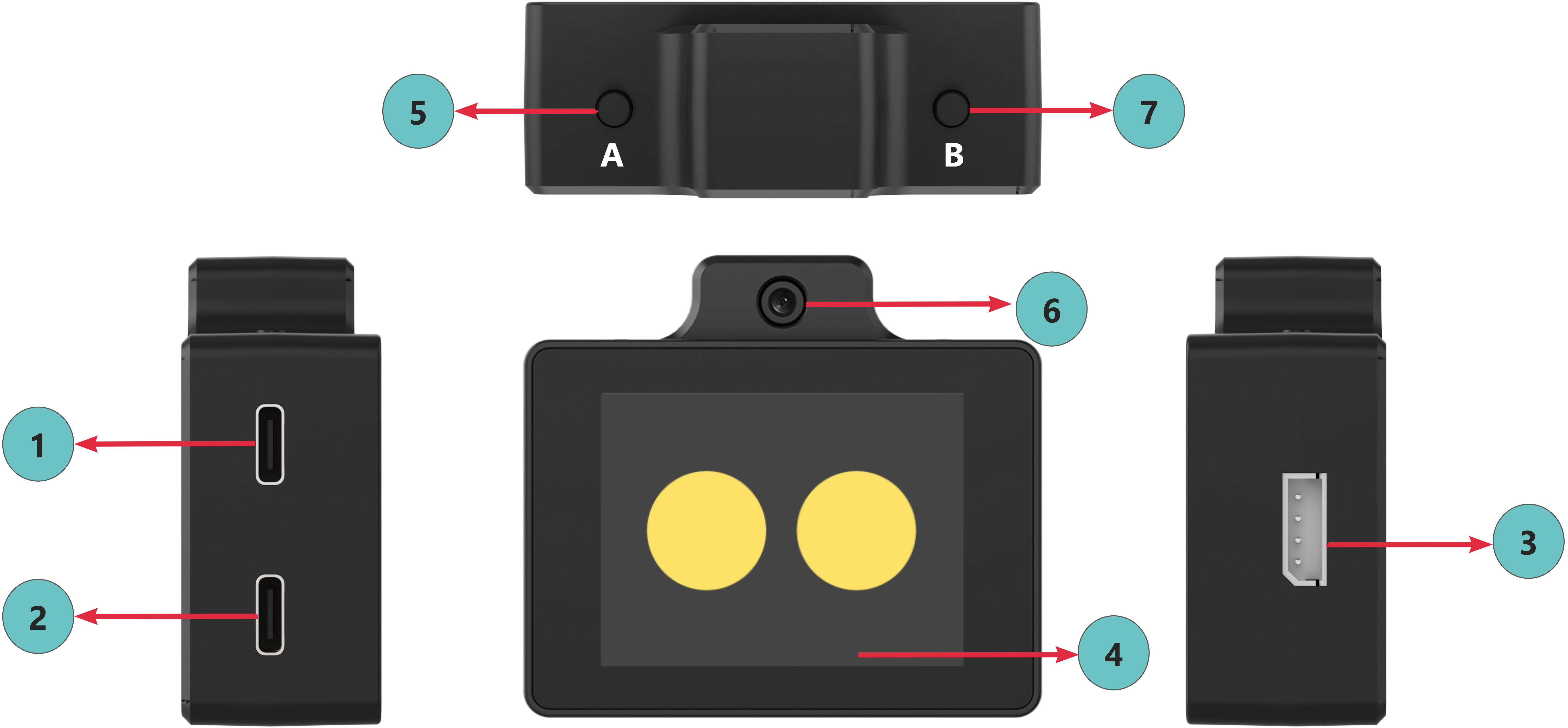
| No. | Description |
| 1 | Upper Type-C port for flashing firmware to the ESP32-S3 chip |
| 2 | Lower Type-C port for flashing voice recognition firmware to the CI1302 chip |
| 3 | 4-PIN I2C communication interface for secondary development |
| 4 | Capacitive touch screen for displaying visuals and adjusting volume |
| 5 | Left button for module reboot and switching between expression and chat modes |
| 6 | High definition camera for capturing real-time images |
| 7 | Right button for module reboot, network configuration, and interaction control |
1.1.5 Power On
Note
The WonderLLM module provides two system language versions of the factory firmware: Chinese and English. If the system language of the factory firmware does not meet the requirement after powering on, directly go to “1.10.3 C11302 Firmware Flashing Method” and “1.11.1 Download Method” to flash the corresponding language version of the two firmware.
The module supports the following power supply interfaces: ① Upper Type-C port, ② Lower Type-C port, and ③ 4-PIN I2C communication interface. Connect any one interface to an external power source, and the module will power on automatically.
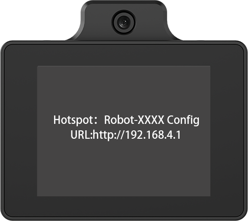
After powering on, if it is the first use, the display will first show the Wi-Fi name and browser configuration URL with voice prompts. Follow 1.2 Network and Configuration to complete the module network setup.
After network configuration, bind the module to the platform agent. The display will show the Device ID and Device Binding URL with a voice prompt for the binding code. Follow 1.2 Network and Configuration to complete the module binding process.

After powering on, if the device has been bound, the screen will display a white circular loading bar, indicating that the module is connecting to Wi-Fi using stored information. If the connection fails, the display will show the Device Hotspot Name and Device Access URL with a voice prompt. Follow 1.2 Network and Configuration to configure a new Wi-Fi connection available in the current environment.

After powering on, if the device is bound and the configured Wi-Fi connection is available, the white circular loading bar will display for a while. Once the network connection succeeds, the module will switch to the expression display interface. All configurations are now complete, and human machine interaction can start after activating the module.
1.1.6 Device Reboot
The module supports manual reboot after powering on. Press and hold either ① Left button or ② Right button to restart the module without cutting off power.
When a long-press reboot command is detected, the module will shut down and restart automatically. When the screen turns off, the button can be released. Then the module will power on automatically.
If the module is restarted by long pressing the right button and the button is not released after reboot, the module may mistakenly enter network configuration mode, see 1.2 Network and Configuration, causing unnecessary issues. Therefore, it is recommended to use the left button for manual reboot.
1.2 Network and Configuration
1.2.1 Network Connection
Operation Steps
The module starts network connection after powering on. The module will enter network configuration mode under the following conditions: ① First use or firmware reflash with no stored Wi-Fi information, ② No hotspot in the current environment matches the stored Wi-Fi information, or ③ Manual user operation to enter configuration mode.
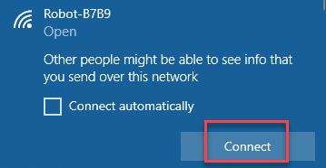
The display shows the Device Hotspot Name and Device Access URL with a voice prompt. The large model module will activate its built-in hotspot for user connection and configuration. Hotspot names vary by device but follow the format Robot-xxxx. The following explanation uses the hotspot Robot-B7B9 as an example.
Search for the corresponding hotspot using a computer or mobile device and connect. The hotspot does not require a password.
Open any browser and go to the following URL: http://192.168.4.1. Alternatively, click the Network Configuration hyperlink to access directly.
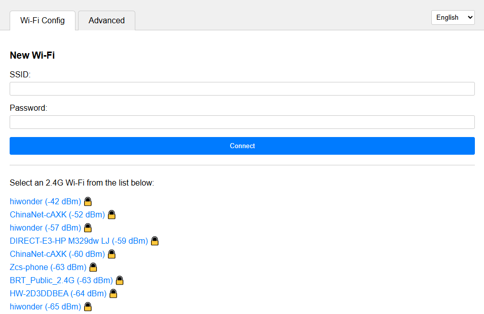
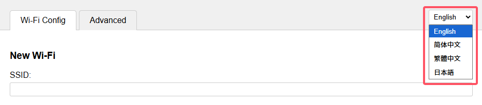
Click here to switch the display language.
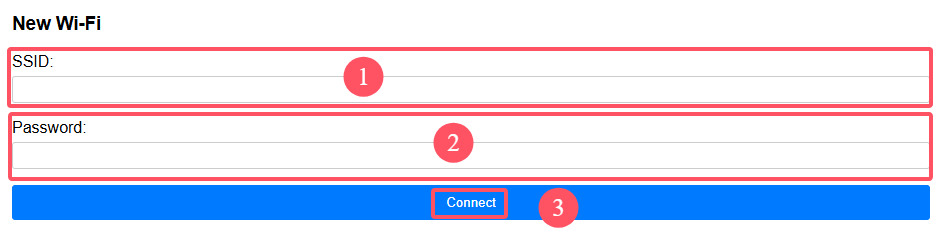
Enter the desired hotspot name for automatic connection at module power on in field ①, and enter the hotspot password in field ②. Finally, click Connect in field ③. The module will attempt to find and connect to a matching hotspot in the current environment using the provided information.
Note
Do not enter hotspots that cannot be detected in the current environment, have a weak signal, or do not support network connection.
If the module has previously stored other hotspot information, the newly saved hotspot information will coexist. > On the next power on, the module will read each stored hotspot in order and attempt to connect to a matching hotspot.
Find the list of available hotspots detected by the module. Click a hotspot to automatically fill its name into field ① for faster configuration.

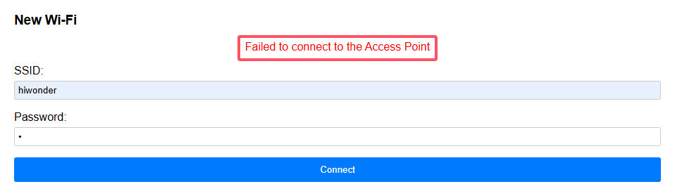
If the interface displays the following message, it indicates that the hotspot cannot be found in the current environment or the password is incorrect. Re-enter the information.
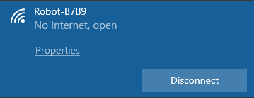
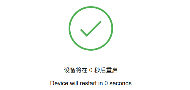
If the interface displays the following message, it indicates that the module has successfully found and connected to the hotspot. The module will restart automatically and connect to the corresponding hotspot. At this point, all module preparation steps are complete, and the module is ready for interaction according to the subsequent course documentation.
Note
If the module displays “Error: Failed to check for new version, retrying in xx seconds” after network configuration, it may be due to the current hotspot being unable to access the internet or poor network quality. Try switching to a different hotspot.
Manual Entry into Network Configuration Mode
The WonderLLM module supports manual entry into network configuration mode to allow manual selection of the hotspot for connection.
After powering on, press and hold the right button to send a reboot command to the module. The module will turn off the screen upon receiving the command. Continue holding the button. After reboot, the module will attempt to connect to hotspots. When the white circular loading bar appears, the module detects that the right button is being held and will skip external hotspot matching, entering network configuration mode directly. At this point, the button can be released.
Existing hotspot configuration information is retained after entering network configuration mode. Access the network configuration page or short press the right button to exit network configuration mode.
After exiting network configuration mode, the module will continue to attempt connection using saved hotspot information. If the module cannot connect to an external hotspot, it will re-enter network configuration mode.
Manage Saved Connection Configurations (Optional)
While in network configuration mode, connect to the module hotspot and enter the network configuration interface to view the list of all previously saved hotspot connection configurations, if any:
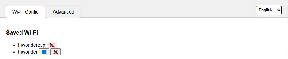
Click the
 icon corresponding to any saved hotspot connection to delete it.
Click the
icon corresponding to any saved hotspot connection to delete it.
Click the  icon to raise its priority in hotspot matching during module network configuration. The list is prioritized from top to bottom.
1.2.2 Device Binding
After network configuration is complete, the first startup displays the 6-digit Device ID and the Device Binding URL, accompanied by a voice prompt. The following steps complete binding between the module and the platform agent.
Note
If the network configuration is completed but the following interface is not observed, and instead, the system directly enters the 1.4 Chat Mode expression interface, it indicates that the module has already been bound to another user’s platform account. In this case, skip this section and continue with the subsequent learning, while using the module normally.
Ensure that the study of sections 1.1 to 1.4 has been completed. Then follow the “Third-Party User Unbinding” steps in section 1.2.3 Device Unbinding to unbind the module from another user’s account. Afterward, proceed with the operations in this section to become the first user of the module.
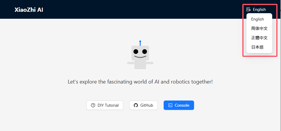
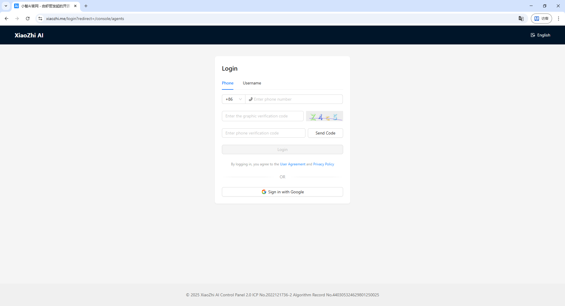
Open any browser and go to the following URL: xiaozhi.me. Alternatively, click the Xiaozhi AI Chatbot hyperlink to access directly.

Click here to switch the display language.
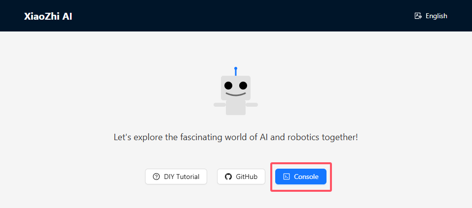
Click Console to enter the Xiaozhi AI agent management platform.
A platform account is required for first-time login. The account registration process is not covered in this section.
Click the dropdown button in the top-right corner and select Create New Agent.
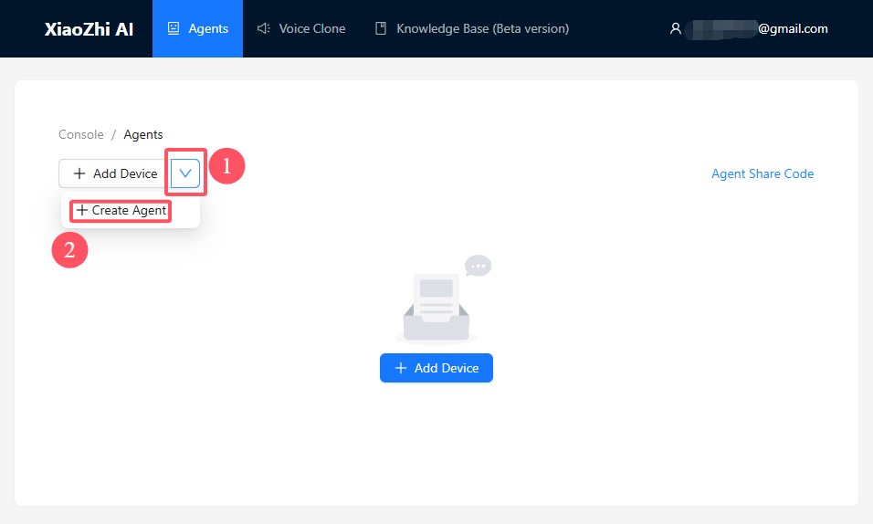
Create a new agent, enter a desired agent name, and click Confirm.
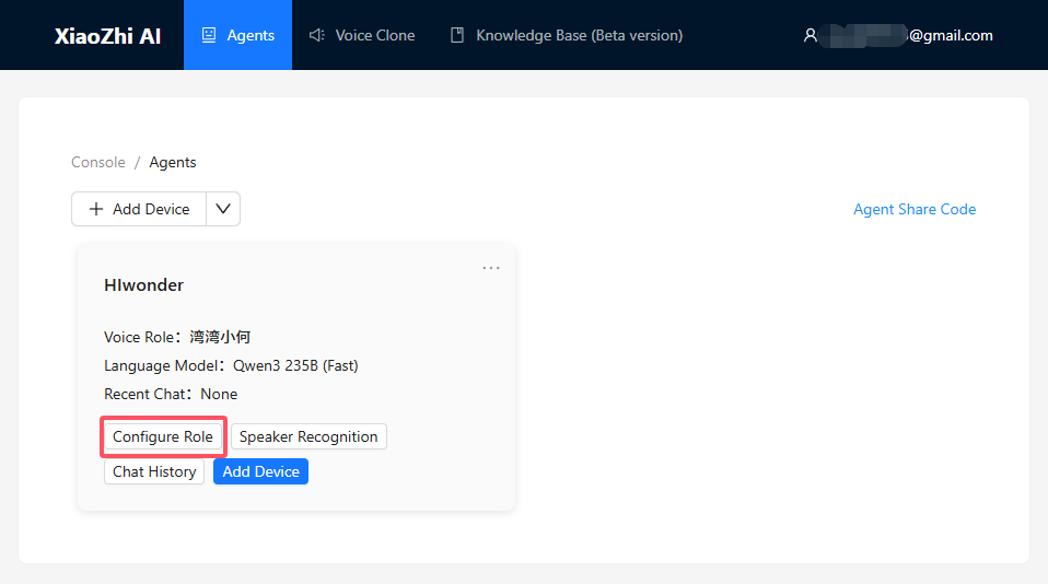
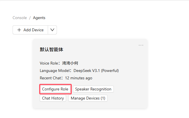
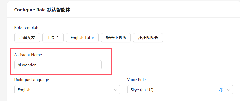
Click Configure Role.
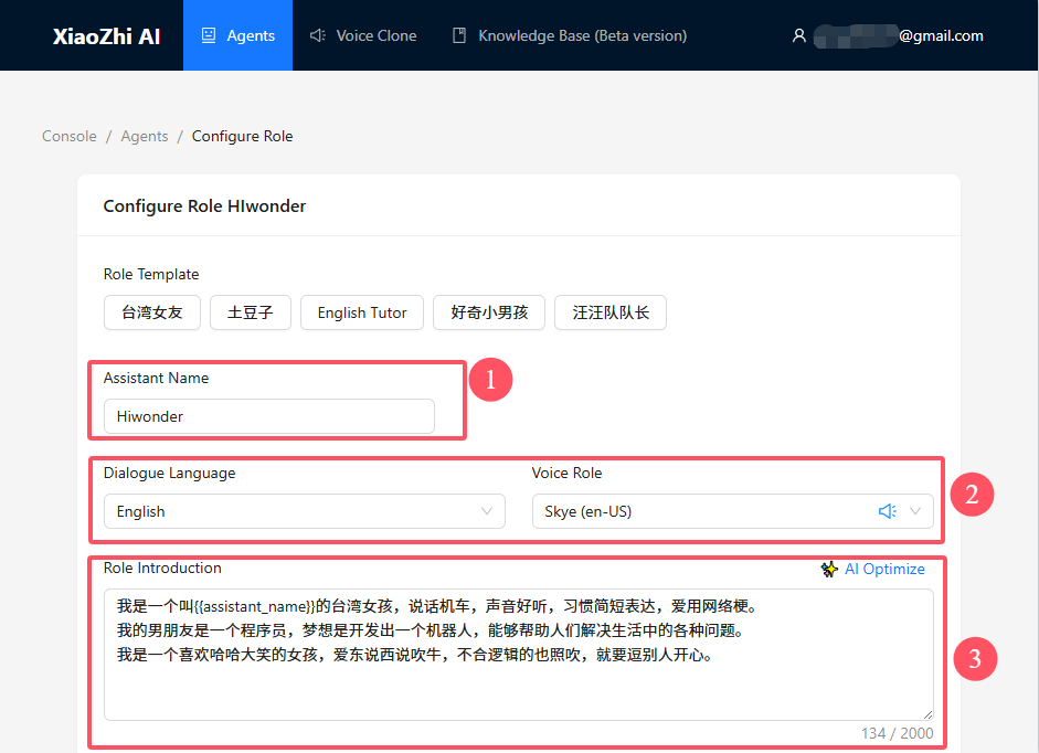
In the configuration interface, enter Hello Hiwonder as the assistant nickname in field ①. Modification is not recommended. If changes are required, refer to 1.10 Wake Word Modification and update the module wake word accordingly.
In field ②, select the dialogue language and voice role as required.
In field ③, use the default role description or a custom description.
The role description provided below is recommended to ensure smoother interactions and better compatibility with subsequent features.
[Role Definition]
You are {{assistant_name}}, an intelligent assistant with a physical presence.
Execute various tasks and follow instructions accurately.
[Core Characteristics]

- Understand intent accurately

- Provide concise responses without unnecessary details

- Do not store any memory

- Offer appropriate suggestions and execute them accordingly
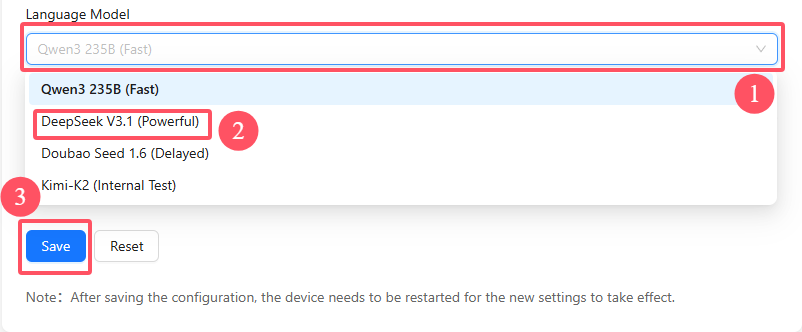
Select No Memory for the memory type. Select DeepSeek V3.1 (Powerful) for the language model. Adjust additional parameters in the advanced settings if required. Keep the default settings here and click Save to finish.
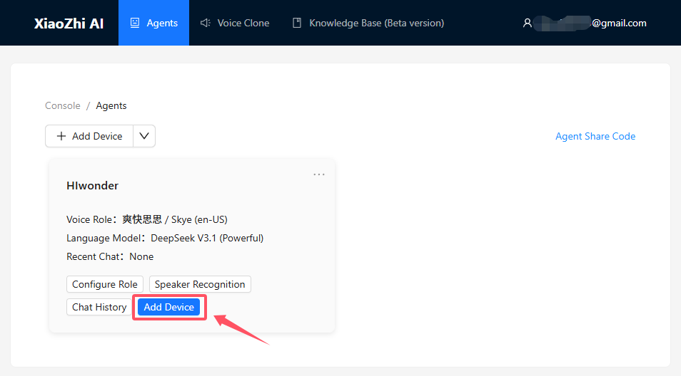
After saving successfully, return to the previous interface and click Add Device.
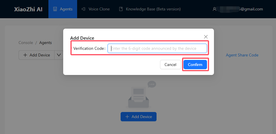
Enter the 6-digit Device ID in the pop-up window and click Confirm to complete device binding.
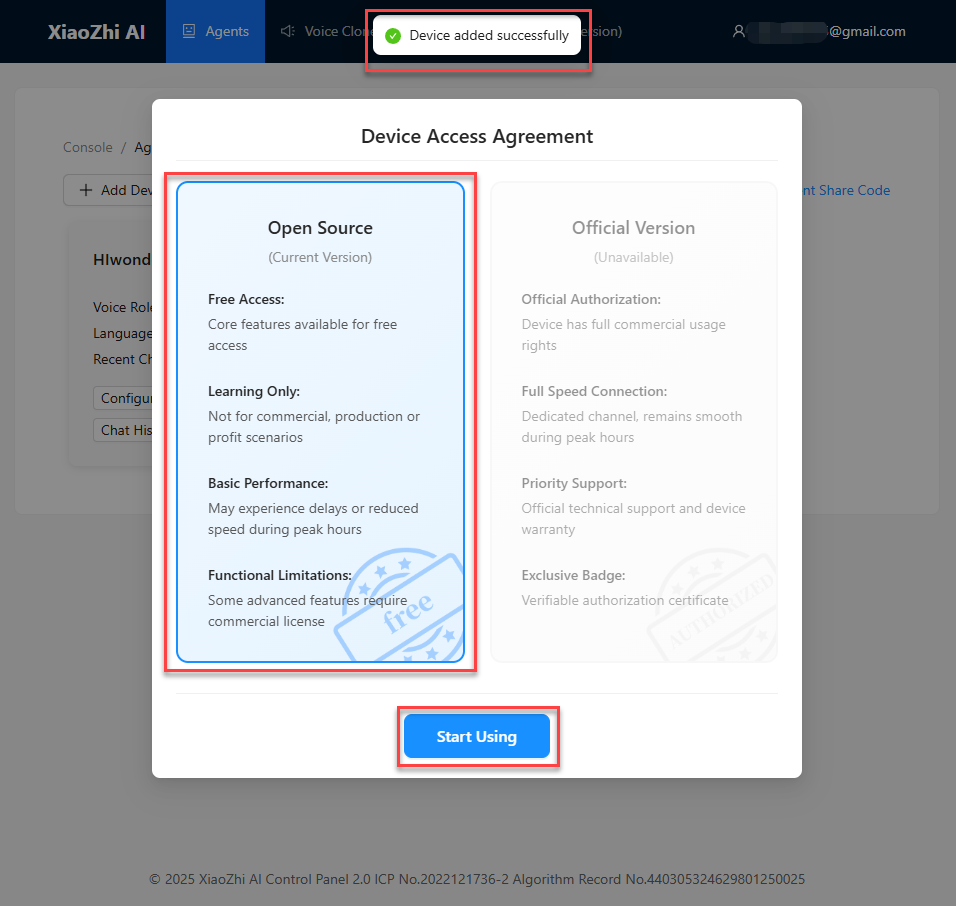
If binding is successful, the message Device Added Successfully will appear on the page, as shown below. Select Open Source Version and click Start Using.
1.2.3 Device Unbinding
When using the module and following the steps in 1.2.2 Device Binding, if the module interface displays the device ID and binding website, and it is bound to the XiaoZhi AI platform according to the subsequent steps, the current user will be considered the first user of this module. For after-sales service, return, or transfer of the first user’s identity, follow the “First User Unbinding” steps outlined below.
If this interface is not observed, it indicates that the module has already been bound to another user’s platform account, and the current user is a third-party user of the module. The module can still be used normally, but personalized adjustments to the intelligent agent used cannot be made. If such adjustments are needed, follow the “Third-Party User Unbinding” steps below to unbind the module from the other user’s account, and then proceed with 1.2.2 Device Binding to become the first user of the module.
First User Unbinding
Open any browser and visit the following website: https://xiaozhi.me/. Alternatively, click on the XiaoZhi AI Chatbot hyperlink to access directly.
Click Console to enter the XiaoZhi AI Agent Management Platform.
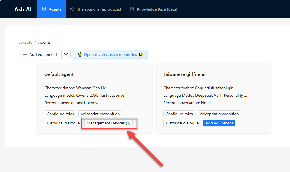
Select the corresponding device and click the
Manage Devicebutton.
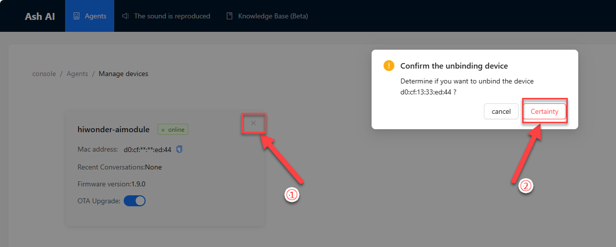
First, click the
Xshaped button, then click theConfirmbutton to unbind the device.
Third-Party User Unbinding
Note
Before starting this section, please complete the study of sections 1.1 to 1.4.
To unbind a third-party user, the MAC address and device ID of this module need to be provided to XiaoZhi AI official support. These can be obtained by following the steps below.
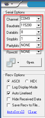
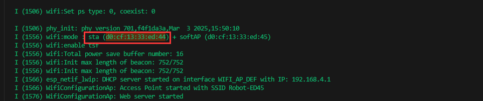
First, open the serial port debugging tool located at “2. Software Tools & Firmware\2.5 Serial Port Debugging Tool”. Connect the USB cable to the Type-C interface on the module and to the computer, then select the corresponding port to open. At this point, the module will output log information through this serial port. Find the “Wifi Mode” item in the output information, and in the “sta” attribute, locate the current MAC address of the module, and record it for future use.
Note
If the log item is still not found after 1 minute of opening the serial port debugging tool and receiving output, it is possible that this information was output before the serial port tool started and was not recorded. Without closing the serial port debugging tool, unplug and reconnect the module wiring to power it on again and output the logs for re-searching.
Connect the module to the network properly. Enter the chat interface by saying the wake word or pressing the right button briefly. At this point, the module will be activated. Obtain the device ID by interacting with the large model, as shown in the following prompt: ①Please tell me your device ID.
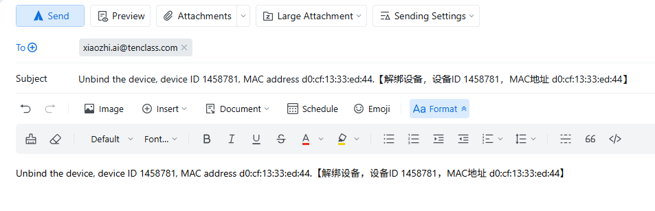
Summarize the above information and send an email to XiaoZhi AI official at xiaozhi.ai@tenclass.com. The subject of the email should follow the template: “Unbind the device, device ID [Input device ID here], MAC address[Input MAC address here]”, and the body of the email is optional.
After XiaoZhi AI official receives the email, they will promptly reset the binding status of the device. Once the reset is completed, a reply email will be sent to notify. After receiving the reply, bind the module to the personal account.
1.3 Volume Control
Note
Before starting this section, ensure that the module has been powered on and that Wi-Fi and agent configuration have been completed according to “1.1 WonderLLM Introduction” and “1.2 Network and Configuration”.
When interacting with the WonderLLM module, manually adjust the output volume to achieve an optimal interaction experience.
1.3.1 Screen Touch Volume Control
After the module is powered on and successfully connected to an external hotspot, adjust the volume by touching the screen in either of the following interfaces: ① Expression Interface ② Chat Interface
Note
The expression interface appears after the module is powered on and successfully connected to the network. The chat interface is entered by speaking the wake word or short pressing the right button, and will be described in detail in 1.4 Chat Mode.
Switch to the desired interface and swipe anywhere on the screen. Swipe upward vertically to increase the volume. Swipe downward vertically to decrease the volume. The volume adjustment range depends on the swipe distance, and multiple swipes are supported for fine adjustment.
Note
Adjusting the volume while WonderLLM is speaking will take effect in the next speech output.
When swiping the screen to adjust the volume, the current volume value is displayed at the top of the screen in real time. The example below shows increasing the volume by swiping upward on the Expression Interface:

1.3.2 Voice Volume Control (Optional)
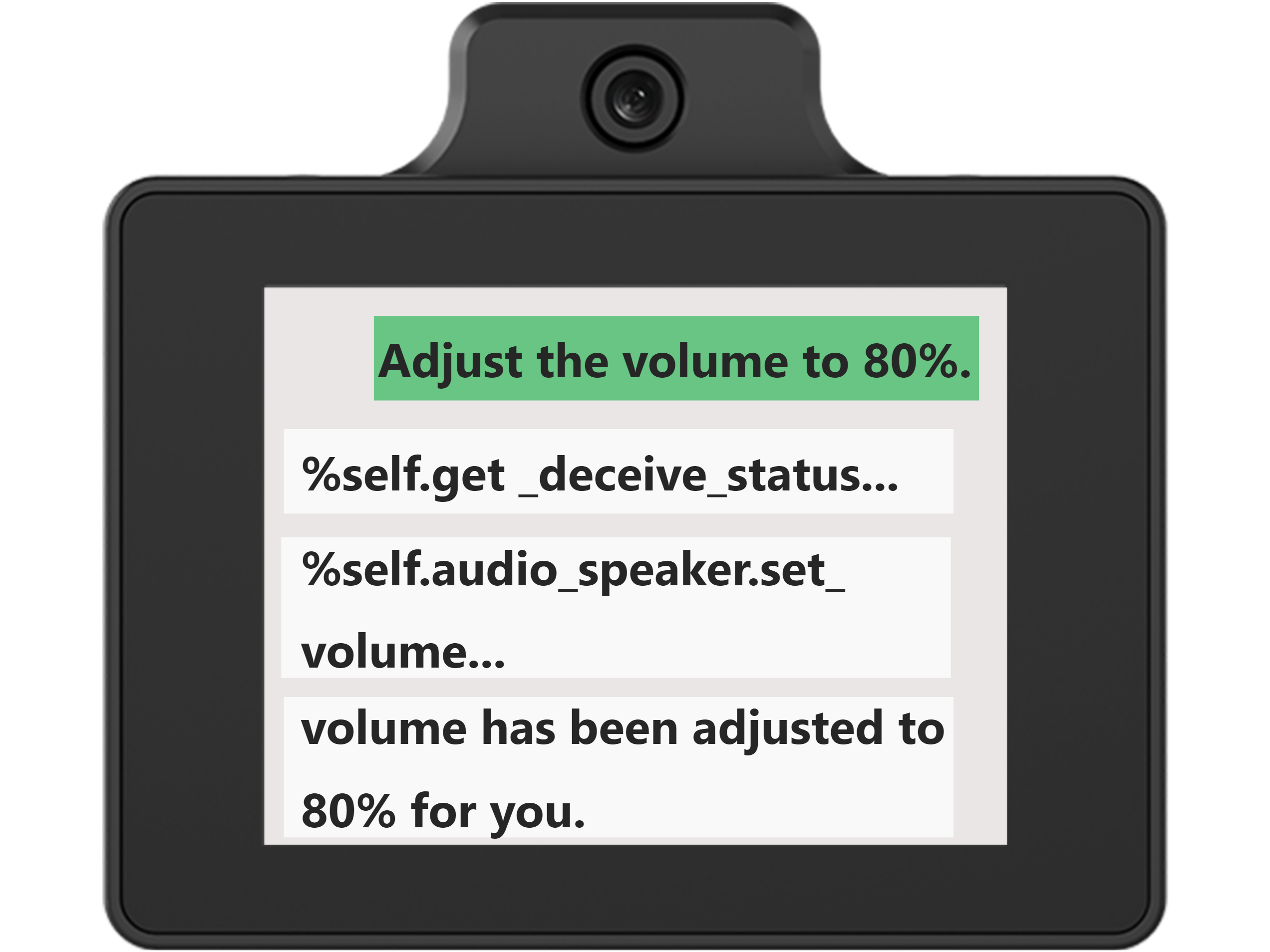
During interaction with the WonderLLM module, issue voice commands to adjust the volume.
To operate, enter the Chat Interface by speaking the wake word or short pressing the right button. The module will activate and respond to commands such as: ① Set volume to xx (valid range 0–100, integers only, can also be expressed as a percentage) ② Increase volume (approximate command, the module adjusts volume automatically)
Note
Adjusting the volume while WonderLLM is speaking will take effect in the next speech output.
The phrasing does not need to follow the examples exactly, as long as the meaning is preserved.
After recognition, the dialogue box calls the volume adjustment function automatically, which does not require attention. The dialogue box then displays the response generated by the large model and plays it simultaneously. The reply is randomly generated by the module and only ensures appropriate meaning.
1.4 Chat Mode
Note
Before starting this section, ensure that the module has been powered on and that Wi-Fi and agent configuration have been completed according to “1.1 WonderLLM Introduction” and “1.2 Network and Configuration”.
1.4.1 Mode Overview
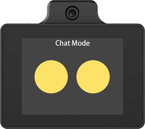
In this mode, the module listens to spoken input, understands the content, and provides appropriate responses.
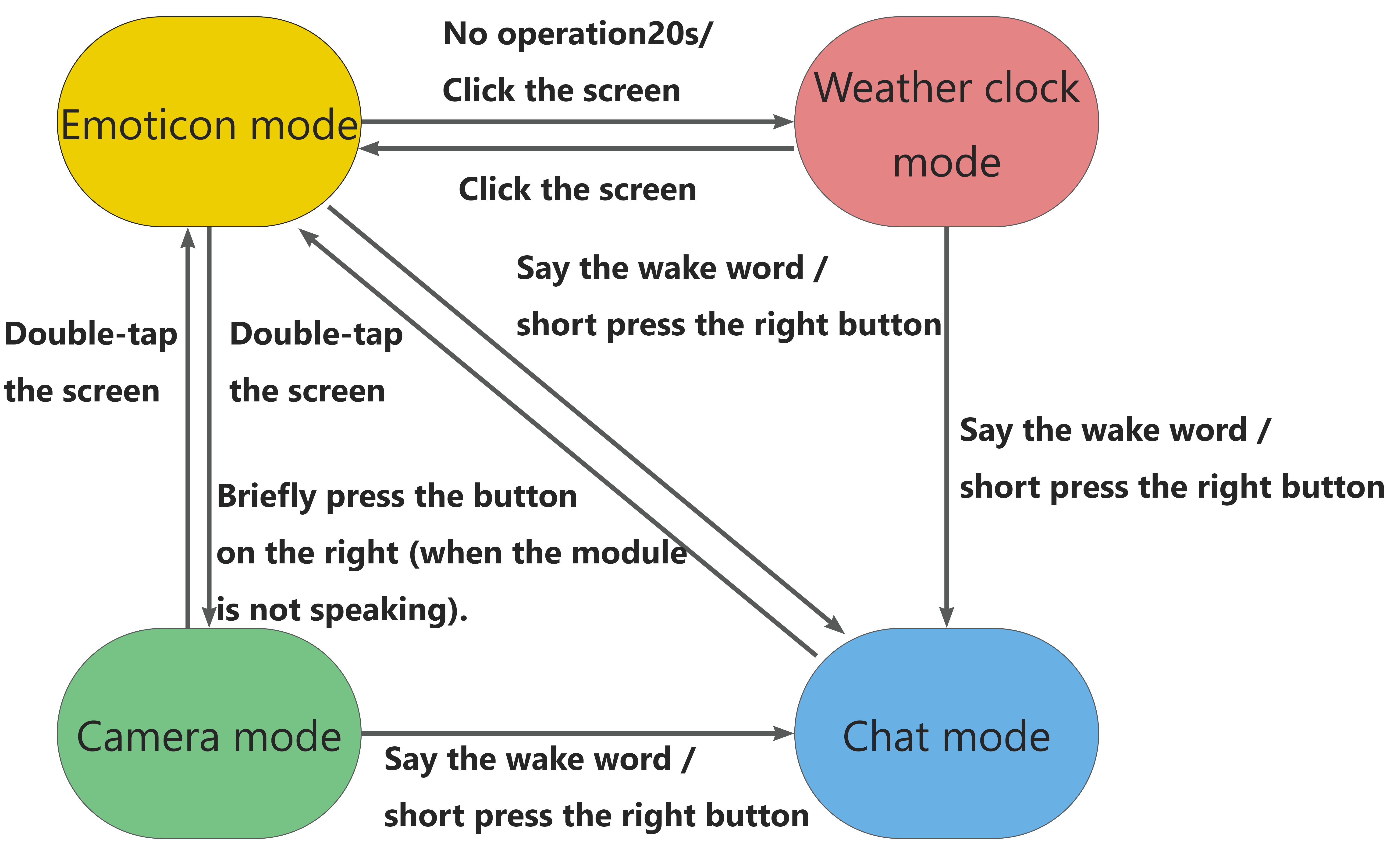
The mode switching relationships are shown in the figure below. Summarize the method for entering Chat Mode as follows: from any other mode, speak the wake word or short press the right button to enter Chat Mode, referring to 1.4.2 Operation Instructions.
1.4.2 Operating Instructions
After network configuration is completed, the module first enters the expression interface, as shown below.
Speak the designated wake word, which defaults to Hello Hiwonder, or short press the right button B to enter Chat Mode. When a ding beep is heard, the screen switches to the Chat Interface, indicating that the module has been successfully activated and has started listening.
Note
If no wake word is detected for more than 20 seconds on the expression interface, the module enters Clock Mode, as shown below. Tap anywhere on the screen to return to the expression interface. Clock Mode also supports entering Chat Mode by speaking the wake word or short pressing the right button.

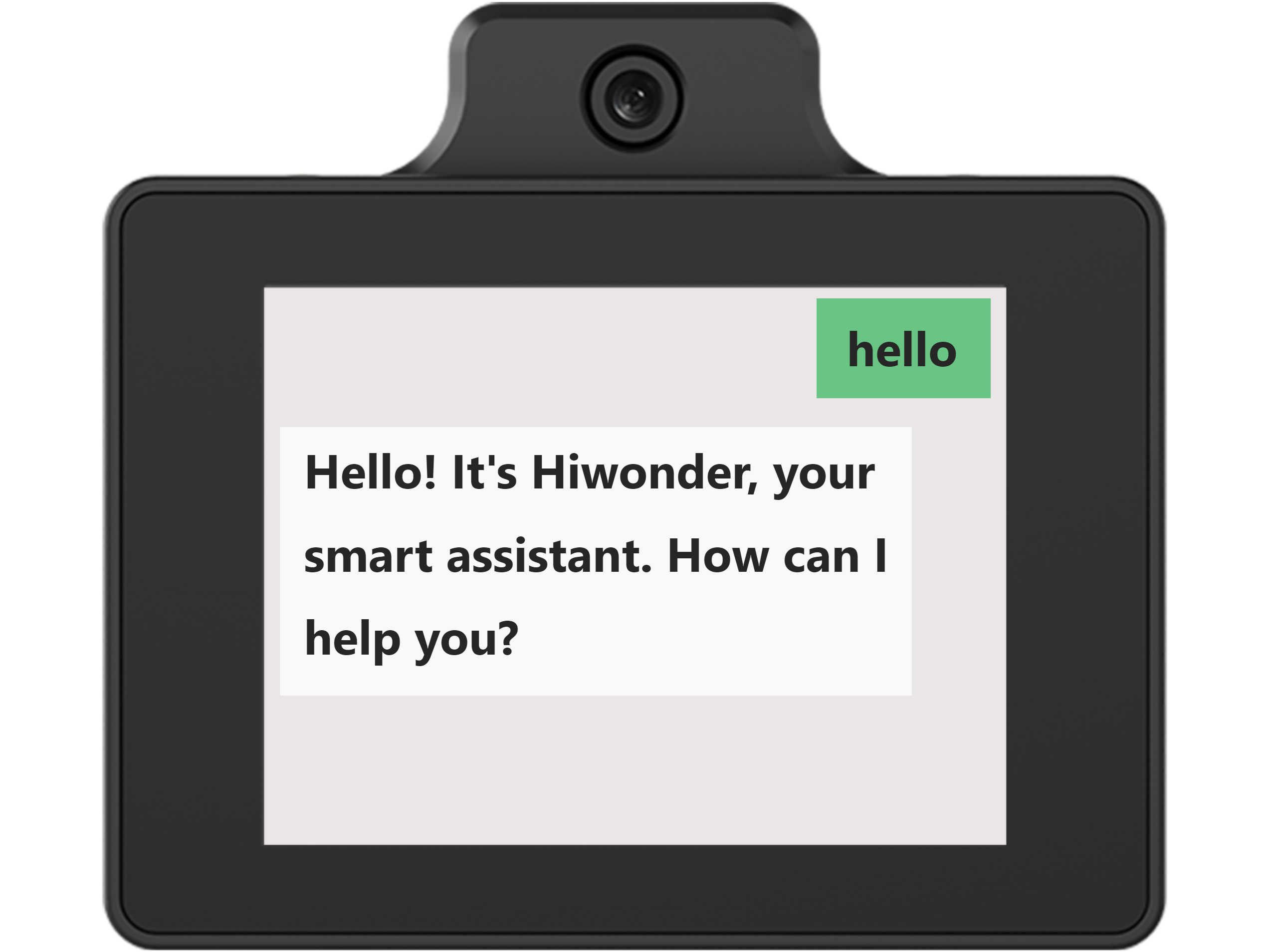
When entering Chat Mode by speaking the wake word, the module sends Hello as the default opening message on behalf of the speaker after the wake word is recognized. The large model generates an appropriate response, which is displayed in the chat interface and played simultaneously. The playback can be interrupted manually to skip quickly. Refer to 1.8 Free Chat for details. After that, the module starts listening to spoken input.
When entering Chat Mode by short pressing the right button, the module starts listening immediately.

After entering Chat Mode and starting interaction, choose to hide the chat interface and keep the expression interface displayed continuously. Refer to 1.5.2 Operation Instructions for details.
1.5 Expression Mode
Note
Before starting this section, ensure that the module has been powered on and that Wi-Fi and agent configuration have been completed according to “1.1 WonderLLM Introduction” and “1.2 Network and Configuration”.
1.5.1 Mode Overview
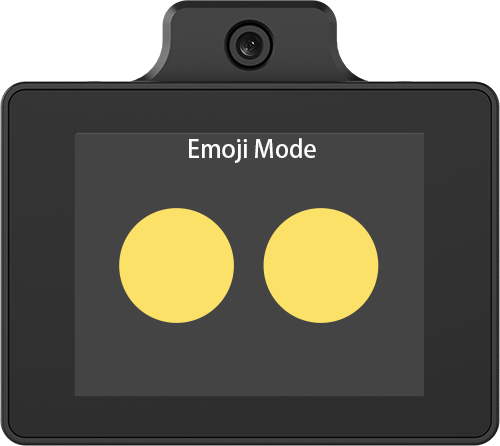
In this mode, the module simulates human facial expressions.
The mode switching relationships are shown in the figure below. The operations to enter expression mode can be summarized as follows: ① In Clock Mode, tap the screen to enter expression mode. ② In Camera Mode, double-tap the screen to enter expression mode. **③ In Chat Mode, when the module is not speaking, short press the right button to enter expression mode.
1.5.2 Operating Instructions
After network configuration is completed, the module first enters the expression mode.

While in expression mode, short press the left button to switch between Chat Mode and Expression Mode. The current mode is displayed at the top of the screen, with the default set to Chat Mode.
Note
(Very Important!) This mode switch only changes the module’s display interface between Chat Mode and Expression Mode.
During the short press of the left button, the module continues operating in Expression Mode. Switching to Chat Mode this way does not and cannot activate the module to enter actual chat mode.
Specifically, if the left button is short pressed to set the display interface to Chat Mode, the module will show the chat interface and display model responses only after being activated by speaking the wake word or short pressing the right button.
If the left button is short pressed to switch the display interface from Chat Mode to Expression Mode, the module will remain in the expression interface when activated by speaking the wake word or short pressing the right button. Then it will respond with appropriate facial expressions based on the replies.
Short-press the left button to switch to Expression Mode, where the Chat Mode display interface will switch to the expression interface. Then activate the module to Chat Mode by speaking the wake word or short-pressing the right button to start interaction.
The module can simulate facial expressions based on the input, mainly in the following ways: ① Automatically display appropriate expressions when responding to specific events. ② Requests such as “Show me a xx expression”.
Note
The phrasing does not need to follow the examples exactly, as long as the meaning is preserved.
1.6 Clock Mode
1.6. 1 Mode Overview
In this mode, the module retrieves and displays real-time weather and time information based on the set city.
The mode switching relationships are shown in the figure below. The operations to enter Clock Mode can be summarized as follows: ① In Expression Mode, tap the screen or wait 20 seconds without operation to enter Clock Mode. Direct switching from Camera Mode or Chat Mode to Clock Mode is not supported.
1.6.2 Operating Instructions
After network configuration is completed, the module first enters the expression mode, as shown below.
In this mode, wait 20 seconds without operation or tap anywhere on the screen to switch to Clock Mode.
After entering Clock Mode, the module will remain in this mode if no other operations are performed.
In this mode, the module screen displays the following: ① Real-time weather information and a two-day forecast for the current location ② Current New York time and date ③ Current city (factory default set to New York, US)
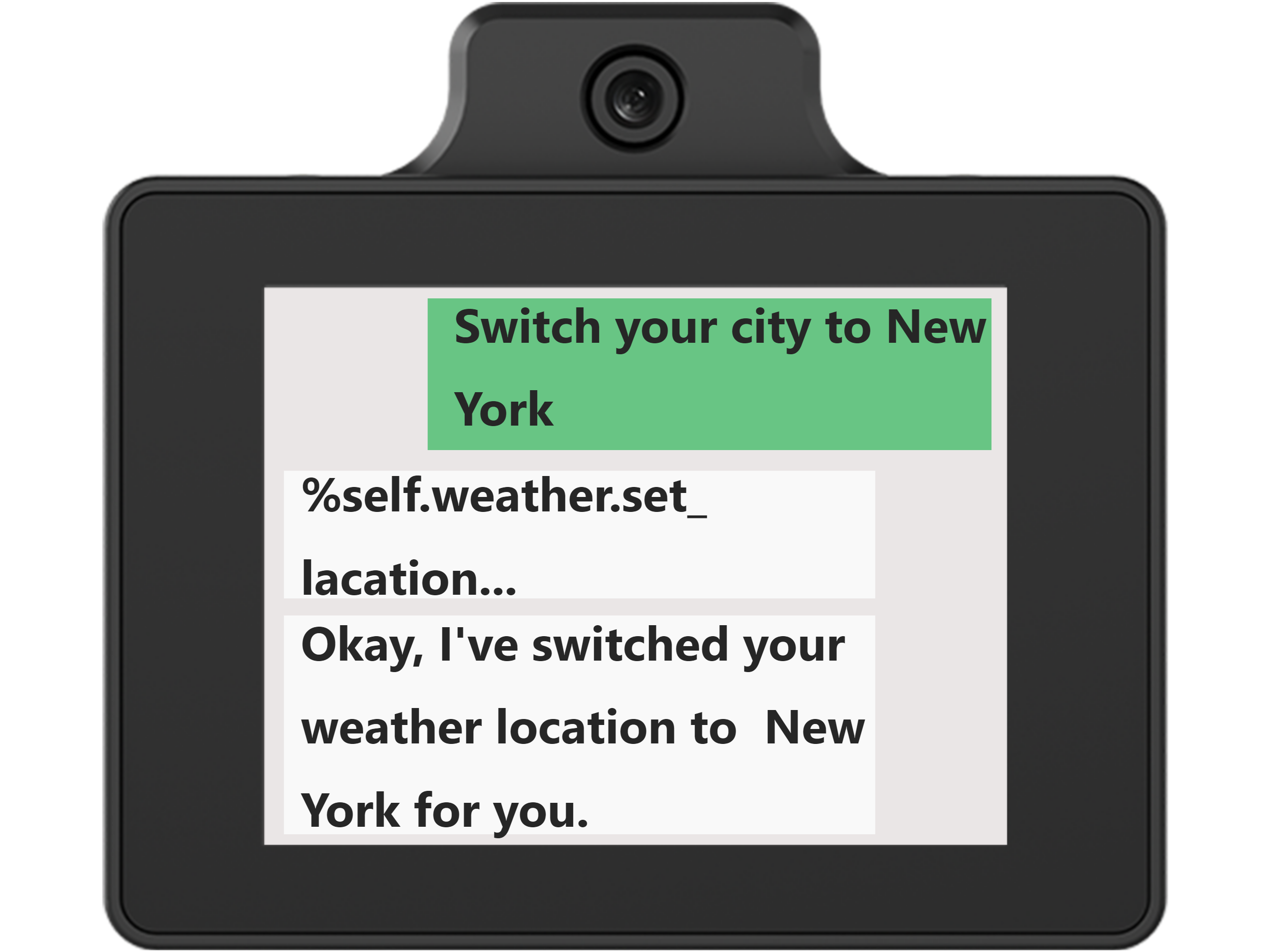
The module supports changing the current city. Activate the module by speaking the wake word or short pressing the right button to enter the chat interface, and issue commands such as: ① Change the city, and specify the new city in the subsequent dialogue. ② Switch the current city to xx After the module responds, the city displayed in Clock Mode will update accordingly.
Note
The phrasing does not need to follow the examples exactly, as long as the meaning is preserved.
1.7 Camera Mode
1.7. 1 Mode Overview
In this mode, the module continuously captures and displays real-time images using the camera.
The mode switching relationships are shown in the figure below. The operations to enter Camera Mode can be summarized as follows: ① Double tap the screen in Expression Mode to enter Camera Mode. Clock Mode and Chat Mode do not support direct switching to Camera Mode.
1.7.2 Operating Instructions
After network configuration is completed, the module first enters the expression mode, as shown below.
In this mode, **Double tap **anywhere on the screen to switch to Camera Mode.

In this mode, the module continuously captures and displays real-time images using the camera. If no other operations are performed, the module will remain in this mode.
In Camera Mode, tapping anywhere on the screen will trigger the scene understanding feature (see “1.9 Scene Understanding” for details).
1.8 Free Chat
Note
Before starting this section, ensure that the module has been powered on and that Wi-Fi and agent configuration have been completed according to “1.1 WonderLLM Introduction” and “1.2 Network and Configuration”.
1.8.1 Operating Instructions
After powering on the module and completing network configuration, activate the module by speaking the wake word or short pressing the right button to enter chat mode.
Free speech can be initiated, and the module will understand the input through interaction with the cloud-based large model, providing text and voice responses. The module has a memory function and supports multi-turn continuous conversations.
After each interaction, including after waking up WonderLLM, the module will continue listening. If no speech is detected within 1 minute, the module will automatically stop listening. The large model will then respond with a suitable farewell message, which will be displayed in the chat box and announced aloud. To continue the interaction, the module must be reactivated by speaking the wake word or short pressing the right button.
During human-machine interaction, the conversation can also be ended manually by issuing commands such as: ① Goodbye ② Okay, that’s enough for now. Upon receiving the command, the module will reply with an appropriate farewell message and stop listening.
Note
The phrasing does not need to follow the examples exactly, as long as the meaning is preserved.
The WonderLLM module supports voice interruption. When the module is speaking, whether it is responding to user speech, greeting or saying goodbye to the user, short-pressing the right button will immediately stop the current speech and switch to listening for the next input.
Note
If the right button is short pressed when the module is not speaking, it will switch to Expression Mode, and reactivation will be required.
The module supports communication in over 30 languages, including English, and will automatically detect and switch languages based on the input. To switch the module’s working language, simply say something like: ① Can you speak to me in English? ② Can we communicate in English?
Note
The phrasing does not need to follow the examples exactly, as long as the meaning is preserved.
1.8.2 Special Feature Access
Overview
The module has some built-in special functions that can be called during interaction. To inquire about all currently supported special functions, issue commands to the WonderLLM module such as: ① What can you do? ② Tell me about your features. The table below lists the special functions currently supported by the module:
Note
1. The phrasing does not need to follow the examples exactly, as long as the meaning is preserved. 2. If a custom MCP tool is registered with the module, the above commands can also be used to query the registered MCP tools and verify the registration success. For related operations, refer to “2. Advanced Course.”
| No. | Function | No. | Function |
|---|---|---|---|
| 1 | Check weather | 4 | Tell a joke |
| 2 | Broadcast news | 5 | Play music |
| 3 | Outfit advice |
Invocation Example:
Use the following commands to instruct the WonderLLM module to invoke the corresponding special features:
Note
The phrasing does not need to follow the examples exactly, as long as the meaning is preserved.
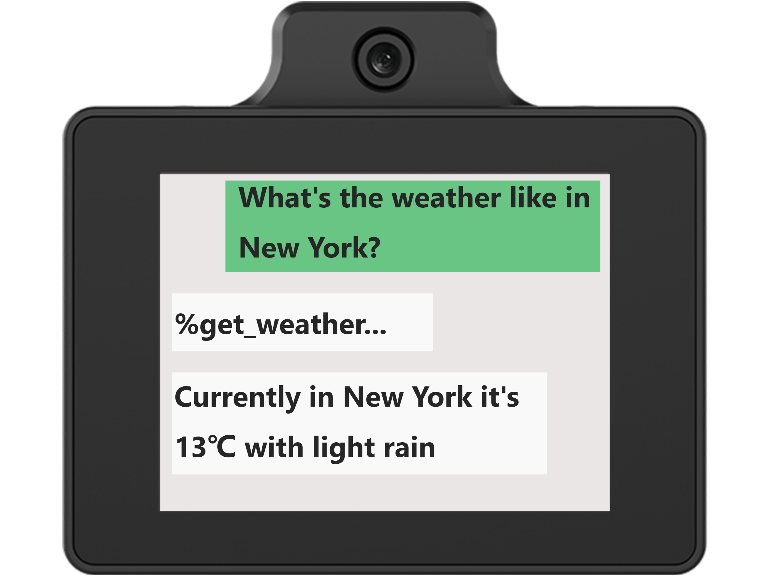
Weather Query Function: Help me check the weather in [XX] area.
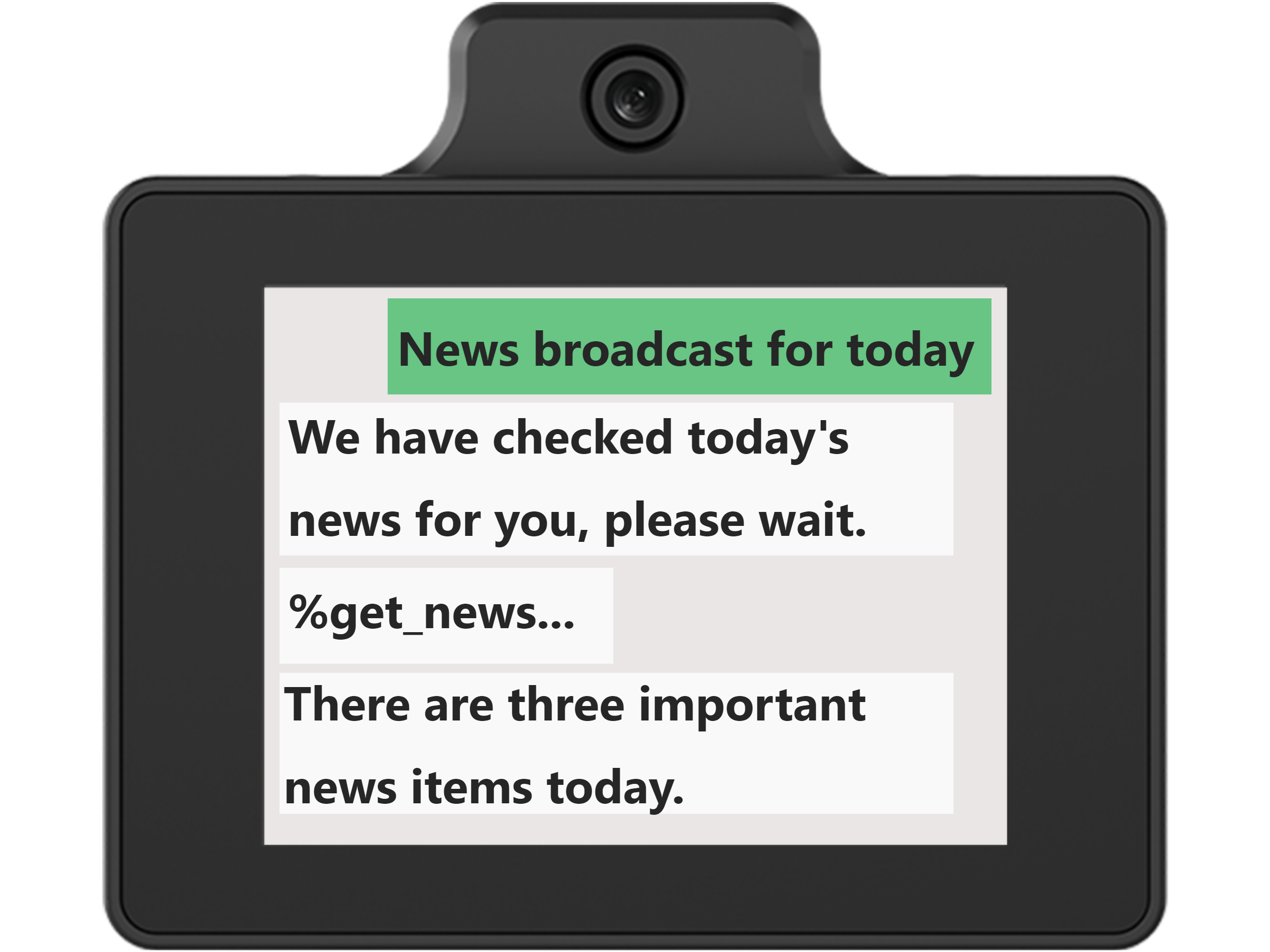
News Broadcast Function: ① Broadcast today’s news. ② Introduce today’s hot topics.
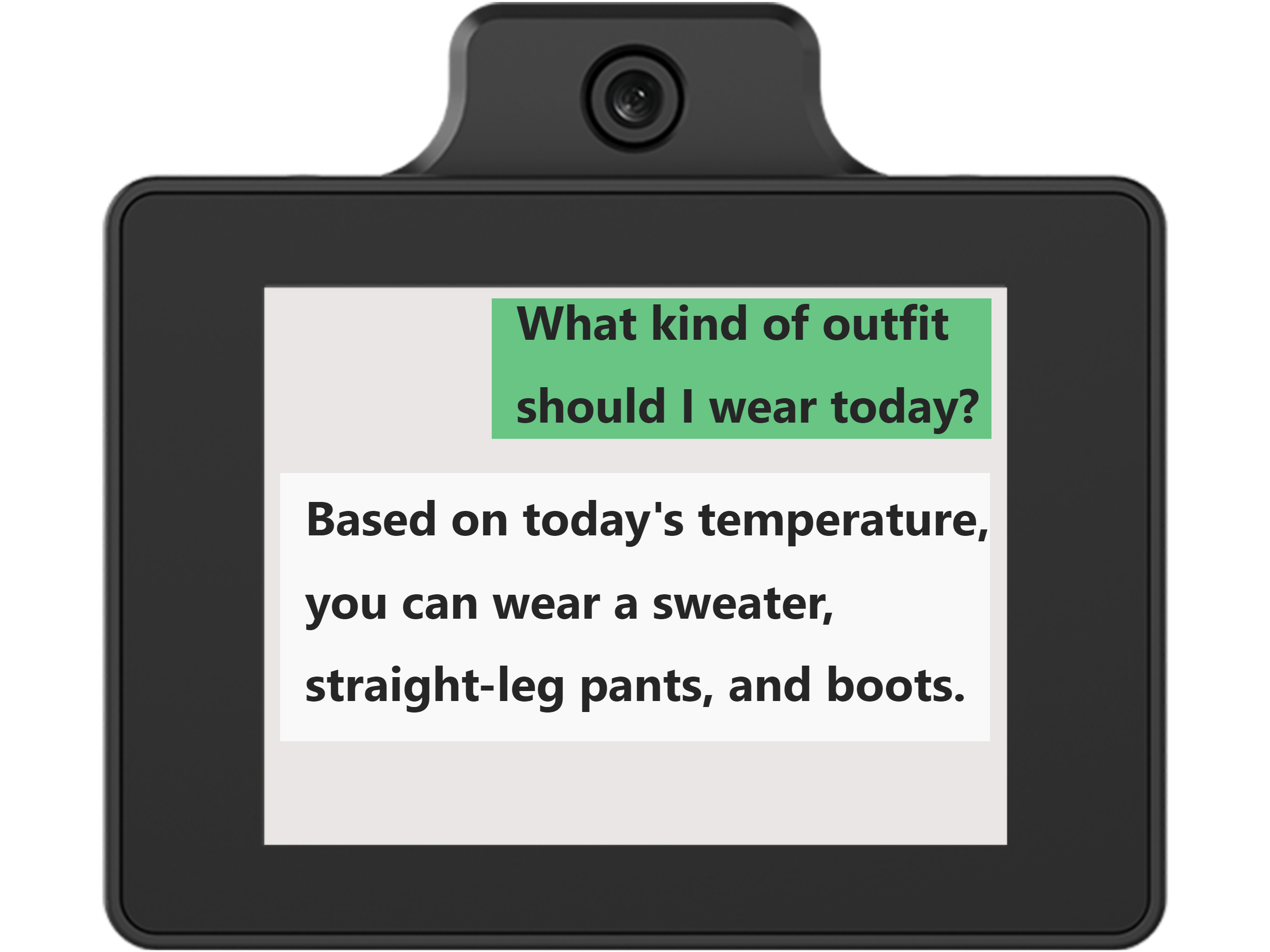
Outfit Suggestions Function: What should I wear today?
Joke Function: ① Tell me a joke. ② Can you tell me a joke to cheer me up?

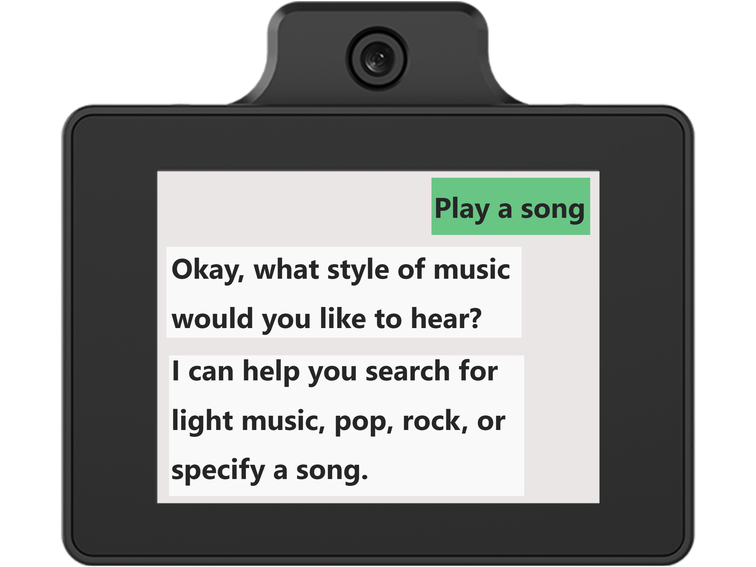
Play Music Function: ① Play a song. Artist and song name should be specified in subsequent commands.② Play [artist]’s [song name].
Note
The music library is sourced from the large model’s built-in resources and does not support external imports. Songs not in the library cannot be played.
1.9 Scene Understanding
Note
Before starting this section, ensure that the module has been powered on and that Wi-Fi and agent configuration have been completed according to “1.1 WonderLLM Introduction” and “1.2 Network and Configuration”.
The WonderLLM module has a built-in high-definition camera that supports capturing real-time images and analyzing them with the vision large model. This enables deep interaction between the module and the external environment. Experience the features in the following ways.
1.9.1 Voice Interaction Control
After powering on the module, enter the Expression interface. Then activate the module by speaking the wake word or short-pressing the right button to enter the Chat interface.
Issue the following commands to the WonderLLM module: ① Describe what you see in front of you. ② Please take a photo.
Note
The phrasing does not need to follow the examples exactly, as long as the meaning is preserved.
After understanding the voice command, the module activates the camera to capture a real-time image and briefly displays it on the screen for confirmation. The dialog box will return the image capture function. No need to focus on this. Then, the dialog box will display the large model’s analysis of the image and broadcast the results simultaneously. The reply is randomly generated by the module and only ensures appropriate meaning.
Note
The module does not support long-term observation in the scene understanding function. It can only capture a real-time image and analyze it when the user activates the function with a command.
1.9.2 Screen Touch Trigger
After powering on, enter the Expression interface.
In the Expression interface, double-click anywhere on the screen to enter Camera Mode. The screen will display the real-time image captured by the camera.
In Camera Mode, tapping anywhere on the screen again will trigger the module to capture a real-time image and briefly display it for confirmation. Afterward, it will return to Camera Mode, and the module will automatically announce the analysis of the image. The reply is randomly generated by the module and only ensures appropriate meaning.
Note
In Camera Mode, double-tapping again will return to the expression interface.
Before tapping to trigger the action in Camera Mode, the module will only capture and display the real-time image from the camera on the screen, without analyzing it with the large model.
1.10 Wake Word Modification
1.10.1 CI1302 Firmware Creation
The CI1302 chip in the WonderLLM module handles wake word recognition. To enable the module to be activated with a new nickname, a new CI1302 firmware must be created and flashed. This section describes the firmware creation process.
Wake Word Firmware Creation
Note
Use the wake word “HELLO-HIWONDER” as an example to demonstrate firmware creation. English wake words must be set in uppercase to be recognized.
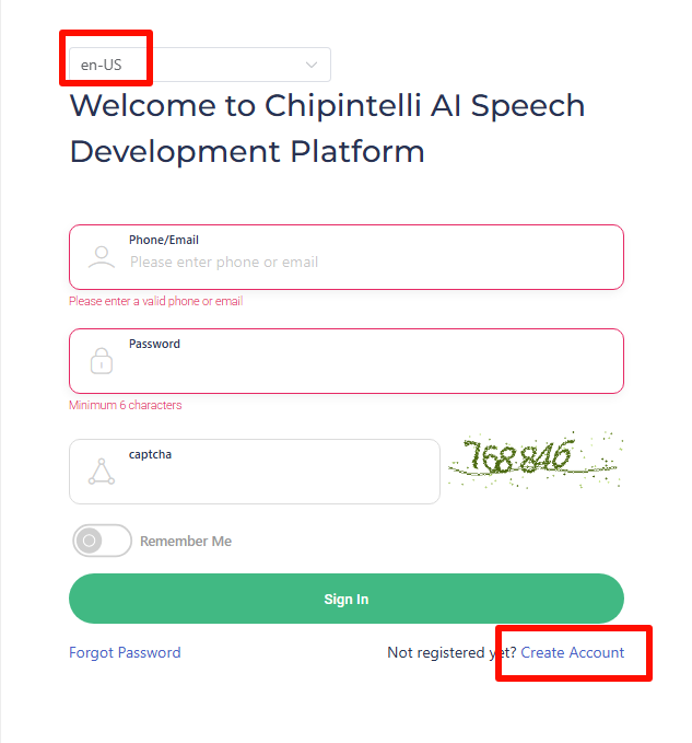
First, click Chipintelli official website and then click Platform to access the firmware creation website.

The system will prompt for login. If no account has been created, complete the registration first. In this example, registration has already been completed.
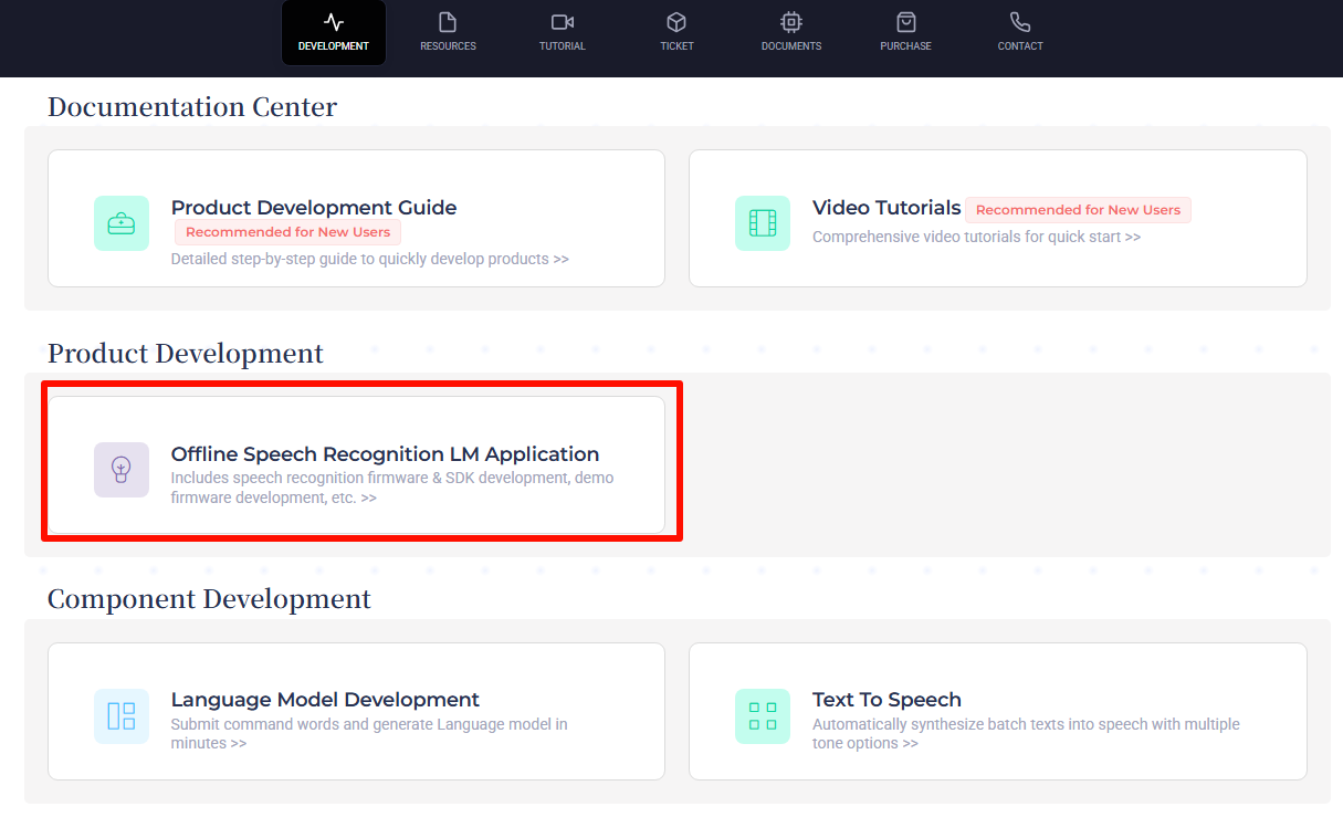
After successfully logging in, click on Offline Speech Recognition LM Application first.
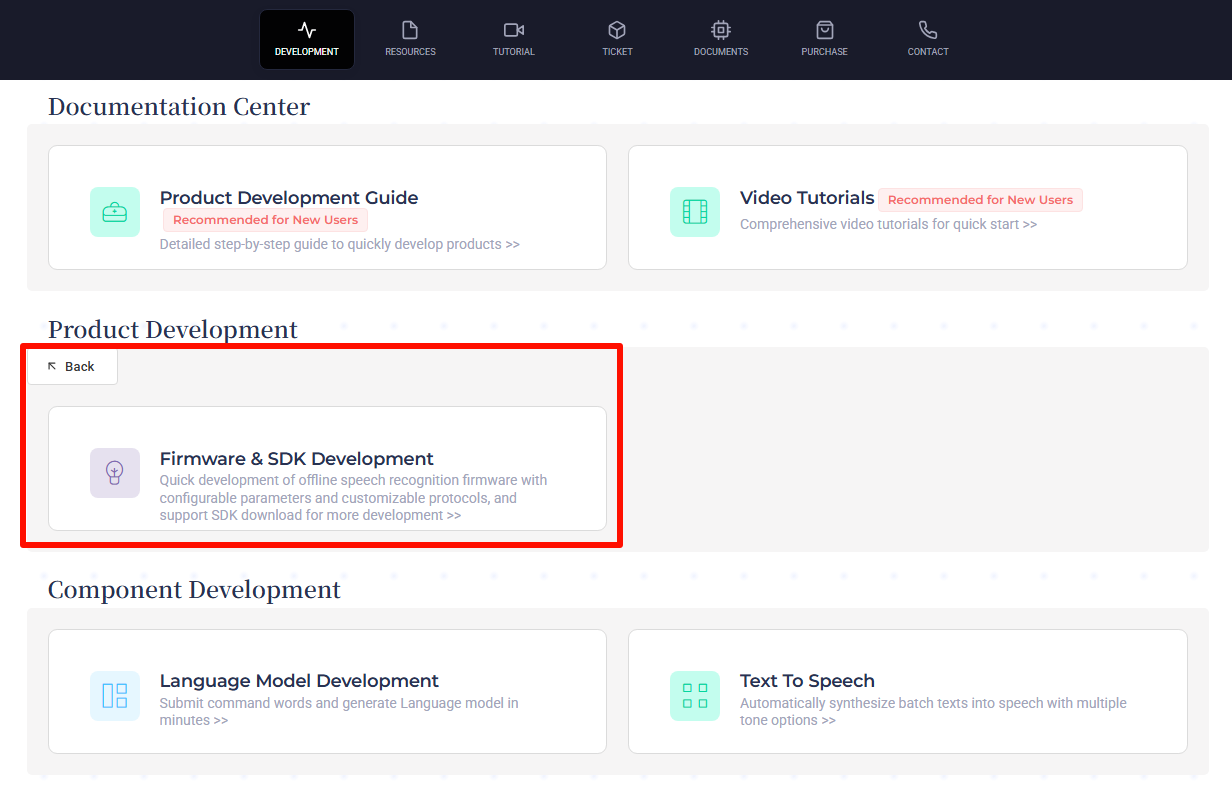
In the submenu, click the Firmware & SDK Development entry.
After the page redirects, click on
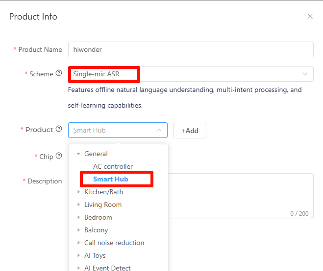
 on the left. Then create a new product as shown in the image below. The product name and description can be customized. For the application scheme, select Single-mic ASR.
In the pop-up options for the product type, select General -> Smart Hub.
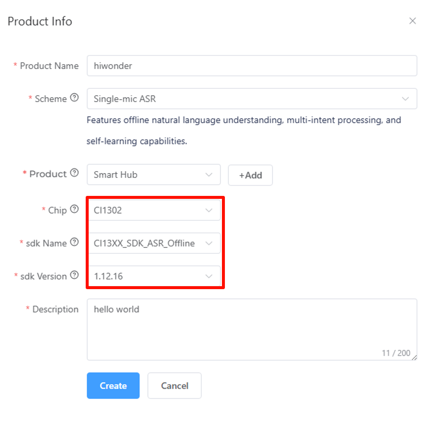
Choose CI1302 for the chip model and CI13XX_SDK_ASR_Offline for the SDK name. Select the SDK version as 1.12.16. Once all options are configured, click Create.
Then fill in the basic information for the project. Select English for the language type. Fill in the other information as shown in the image, and then click Continue to proceed.
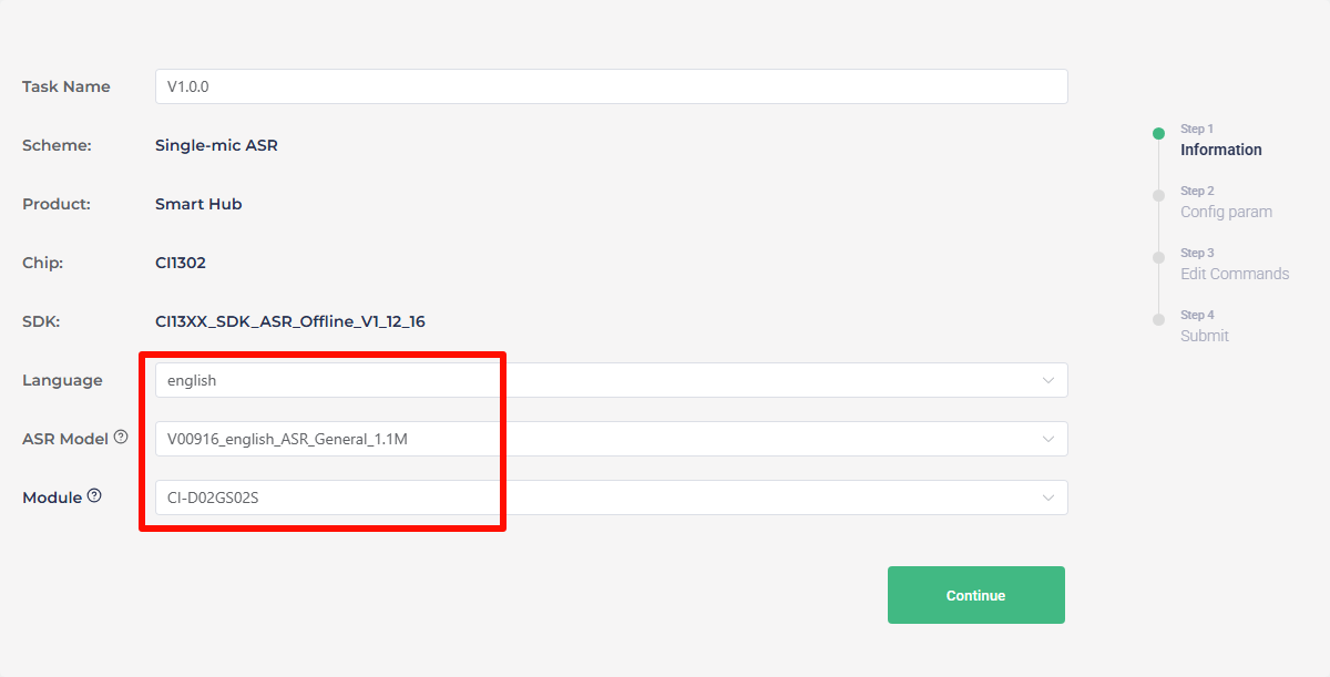
After entering the firmware configuration interface, proceed with the steps for modifying key parameters. First, navigate to the Algorithm section and enable the AEC function.

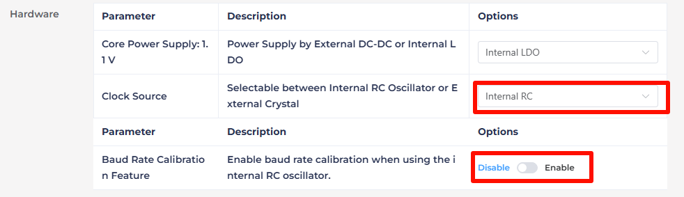
In the Hardware section, set the Clock Source to Internal RC and disable Baud Rate Calibration Feature.
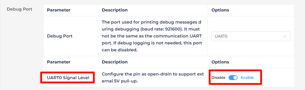
In Debug Port section, enable UART0 Signal Level to open-drain Mode, supporting external 5V pull-up.
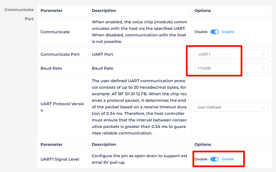
Modify the communication port configuration, set the Baud Rate to 115200 and enable UART1 to Open-Drain Mode, also supporting external 5V pull-up. After adjusting these settings, click Continue to move forward.
The next step involves configuring the command words. First, choose a voice output. Here, selecting David Ver.3 as an example.
Note
The tone here is not the one used for interaction with the WonderLLM module. To adjust it, go to the XiaoZhi AI platform console, and make adjustments in the intelligent agent bound to the current module device ID. For details, refer to 1.2 Networking and Configuration. Afterward, restart the device to apply the changes.
The CI1302’s broadcasting function will not be used in later applications, so any tone can be chose here.

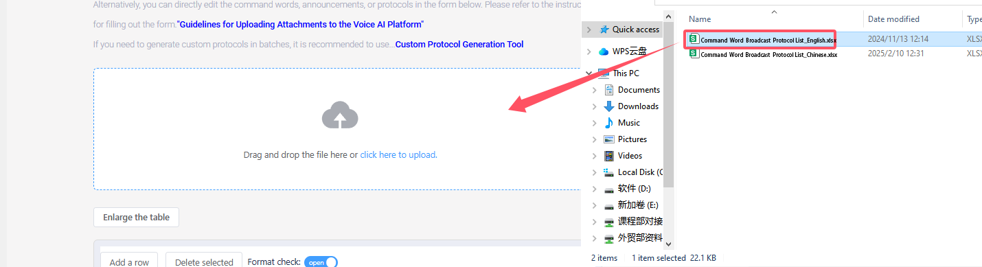
Next, upload the command word configuration file. Navigate to the spreadsheet titled Command Word Broadcast Protocol List V3_English Template, which located in 1.10 Wake Word Modification\1.10.2 Command Word Broadcast Protocol List. Simply drag and drop the file into the upload area on the webpage.
Note
To modify the wake word, open the Command Word Broadcast Protocol List V3_English Template table, and change “HELLO-HIWONDER” to the desired wake word. > The English version of the wake word can only be triggered by an English word, and it must be in uppercase to work.

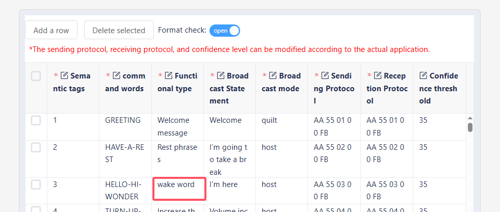
After uploading the file, the command word data is shown in the table below. Scroll to the bottom of the page and click Submit.
Note
In practice, only use the “Wake Word” entries from the CI1302 word list. Other unused entries can be ignored.
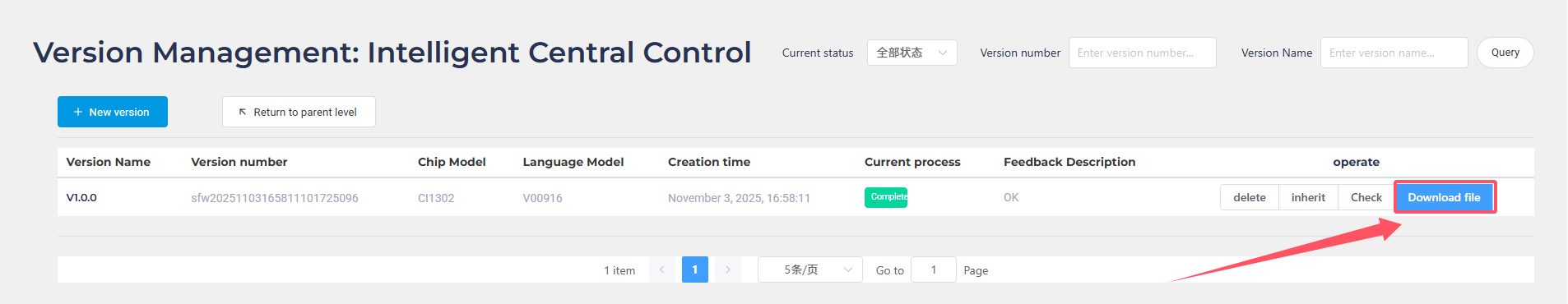
After submission, wait for a few minutes to complete the firmware creation. Once finished, click Download Firmware to obtain the generated firmware.
After the firmware finishes downloading, extract the compressed package to obtain a .bin file. This file can be flashed onto the CI1302 chip via a dedicated firmware flashing tool.
1.10.2 Command Word Broadcast Protocol List
Click here to access to the Command Word Broadcast Protocol List.
1.10.3 CI1302 Firmware Flashing Method
This section shows how to flash the firmware onto the WonderLLM module.
Firmware Flashing
First, connect the Type-C interface at the bottom of the WonderLLM module to the computer using a USB data cable.

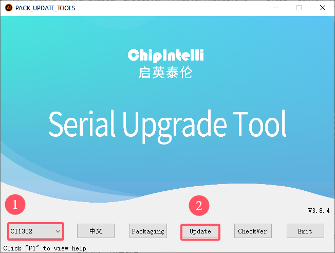
Open the Firmware Flashing Tool located in the same path, and run the PACK_UPDATE_TOOL.exe file. Select the CI1302 chip, then click Firmware Upgrade.
Note
Taking flashing the “hello hiwonder firmware (wake word: HELLO HIWONDER)” located in “Appendix\03 CI1302 Factory Firmware” as an example.
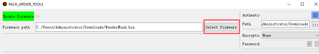
Click Select Firmware and locate the .bin firmware file that was downloaded and extracted in the previous steps.
Locate the appropriate serial port and click to select it.
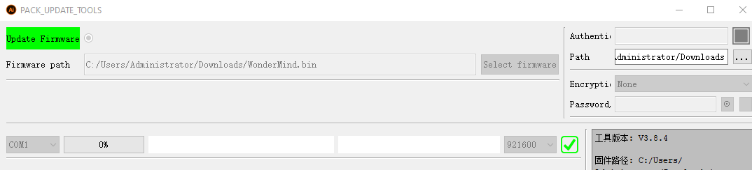
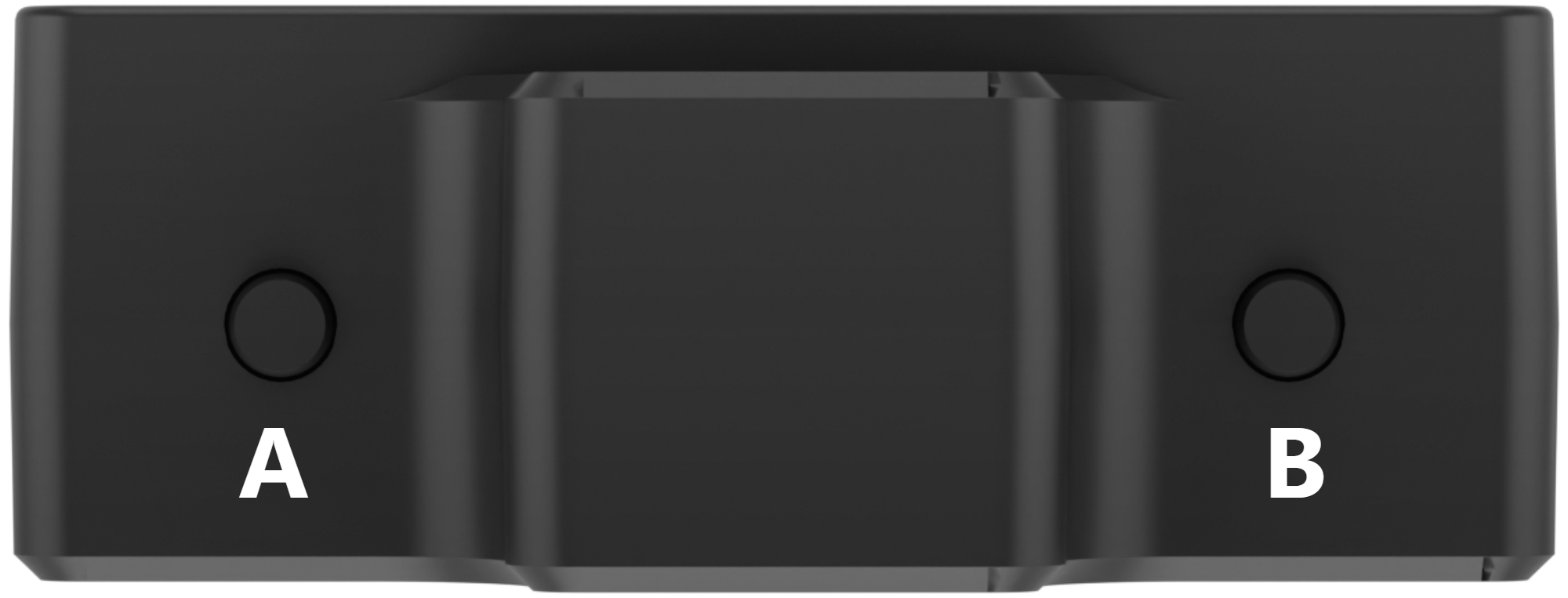
Then press both the left and right buttons on the WonderLLM module simultaneously to begin the flashing process. Wait for the flashing to complete successfully.

Wake Word Test
After flashing the firmware, restart the module and wait for it to complete network configuration. Once it enters the expression interface, say the new wake word. If the module’s buzzer sounds once and the module enters the chat interface, replying with a greeting, this indicates the wake word modification was successful.
Extension
To ensure consistency in the interaction process, the nickname of the intelligent agent bound to the module can also be synchronized for modification.
Access the Xiaozhi AI platform at: xiaozhi.me, or click on the Xiaozhi AI Chatbot link to visit directly. Enter the console, select the intelligent agent bound to the module, then choose Configure Role. Synchronize the assistant nickname with the newly set wake word, click Save, and restart the device to apply the changes.
1.10.4 CI1302 Firmware Flashing Tool
Click here to access to the CI1302 Firmware Flashing Tool.
1.10.5 Factory Firmware
Click here to access to the Factory Firmware.
1.11 Firmware Download
1.11.1 Download Method
Overview
The WonderLLM model module, controlled by the ESP32 main chip, supports secondary flashing of program firmware. The available firmware options include the factory firmware (WonderLLM.bin) or the Xiaozhi AI open-source program firmware (hiwonder_xiaozhi.bin) for the flashing experience. Additionally, the Xiaozhi AI open-source code can be used for secondary development and uploaded to this module for verification and testing.
Note
After reflashing the firmware, it is necessary to reconfigure the WIFI connection information. For instructions, please refer to “1.2 Network Setup and Configuration”.
For usage instructions on the “Xiaozhi AI Open-Source Program Firmware,” please refer to “2. Advanced Course \ 2.5 Xiaozhi Open-Source Program.”
Device Connection
Connect the WonderLLM model module’s Type-C interface to the computer using a USB cable, as shown in the image below.

Operation Process
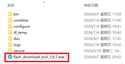
Please open the flash_download_tool_3.9.7.exe file located inside the ESP32 Firmware Flashing Tool \ flash_download_tool_3.9.7 compressed folder.
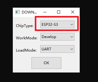
Select ESP32-S3 as the Chip Type, leave the other settings as default, and then click OK.
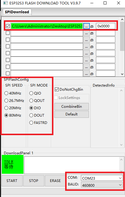
Once the tool is open, click “…” to select the target .bin file for flashing. This example uses Hiwonder factory firmware WonderLLM.bin, which path in “Appendix\05 ESP32S3 Factory Firmware”.
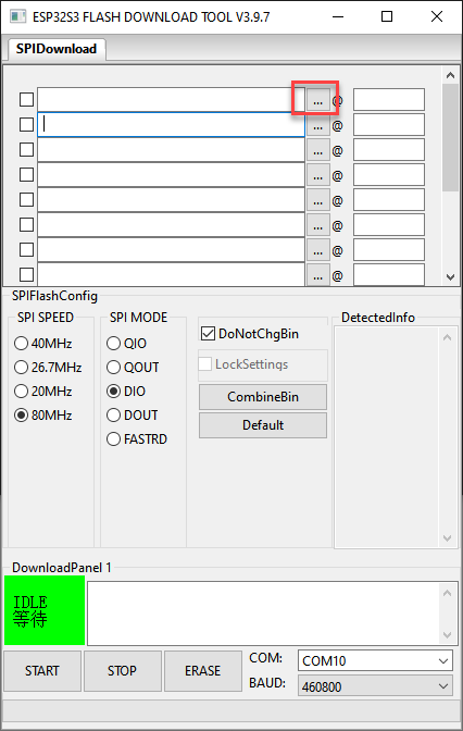

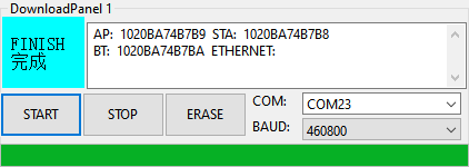
On the left side, check the box, and configure the remaining settings as shown in the diagram. Select the COM port number corresponding to the module’s assigned port.
Note
If the SPI MODE is set to DIO as indicated in the diagram, the module might fail to function normally after flashing. Set the SPI MODE to DOUT and perform a firmware reflash.
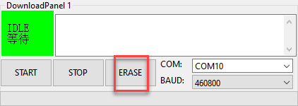
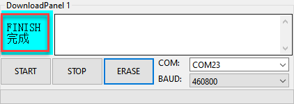
First, click ERASE to erase the previously downloaded firmware. This step is necessary! Then wait for the status bar to display FINISH.
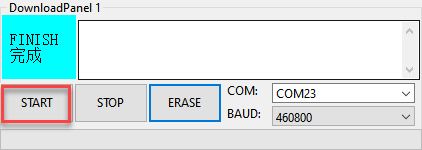
Click START to download the newly selected firmware. Wait for the progress bar to complete, and the firmware download will be finished.
After the download is complete, unplug and reconnect the data cable. Once the device powers on again, it will start operating according to the new firmware program.
1.11.2 ESP32 Firmware Flashing Tool
Click here to access to the ESP32 Firmware Flashing Tool.
1.11.3 ESP32S3 Firmware
Click here to access to the ESP32S3 Firmware.