11.LeArm AI + Conveyor Belt Course
11.1 Conveyor Belt Overview & Installation
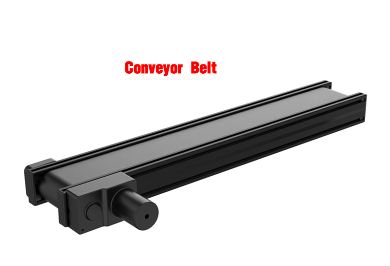
11.1.1 Product Introduction
The electric conveyor belt features a high-quality DC gear motor combined with an industrial-grade PVC conveyor belt and an aluminum alloy frame. It provides smooth and stable transport of various target objects without requiring an external power supply. By simply powering the motor, users can control both the direction and speed of the conveyor belt—making it a true plug-and-play solution.
This product is compatible with most multi-degree-of-freedom robotic arms and linkage-based bionic arms available on the market, making it an excellent choice for AI-powered automated object sorting scenarios.
11.1.2 Product Specifications
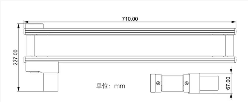
Mechanical Specifications
Unit: mm
Operating Specifications
| Product | Electric Conveyor Belt | Load Capacity | Approx. 9 kg |
|---|---|---|---|
| Rated Voltage | 12 V | Rated Current | 2.5 A |
| No-Load Current | 0.8 A (Starting Current: 1.3 A) | Gear Ratio | 1:70 |
| Maximum Speed | 50 mm/s | Effective Transport Length | 694 mm |
| Product Dimensions | 710 × 227 × 67 mm | Net Weight | Approx. 3.7 kg |
| Package Weight | 4.5 kg | Package Dimensions | 780 × 300 × 120 mm |
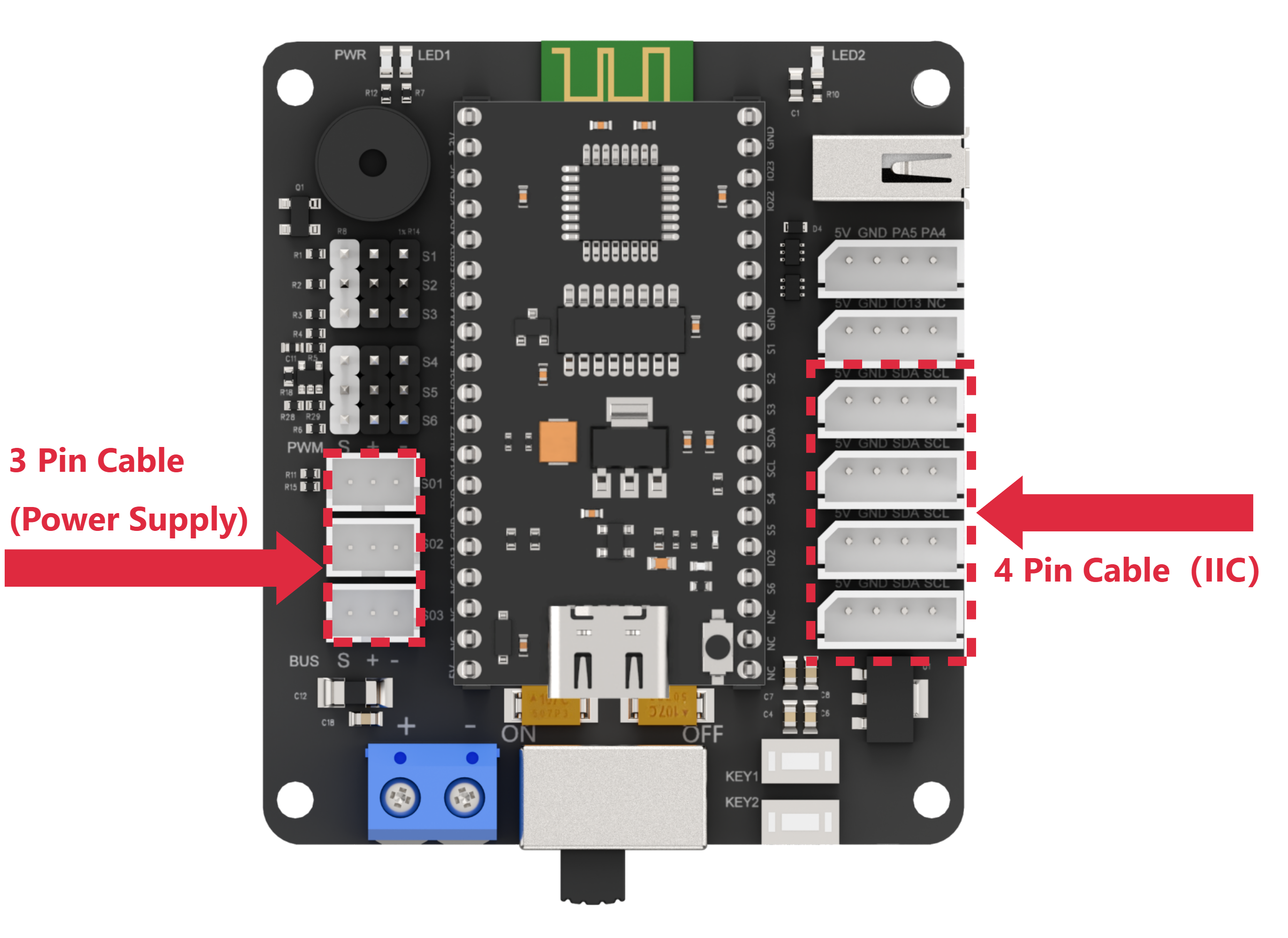
11.1.3 Conveyor Belt Installation
Connect the 3-pin cable of the conveyor belt to any bus servo port on the left side of the diagram for power supply, and connect the 4-pin cable to any IIC port on the right side of the diagram for communication.
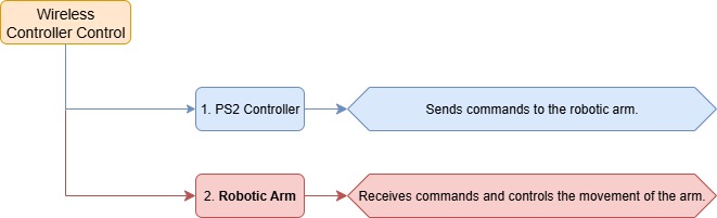
11.2 Wireless Controller Control
11.2.1 Project Introduction
In this lesson, a wireless controller is used to control both the robotic arm and the conveyor belt.
11.2.2 Project Process
11.2.3 Module Instruction
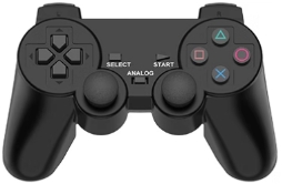
The PS2 controller communicates with the controller via a receiver using a 2.4G wireless signal. The controller has two modes, which can be toggled using the MODE button.
11.2.4 Program Download
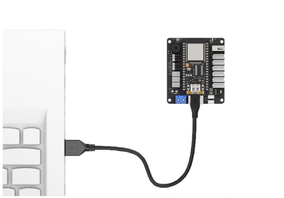
(1) Connect the core board to the computer using a USB cable.
(2) Locate the corresponding Arduino project file in the same directory as this document.

(3) Select the development board model when you open the program, and the specific model is shown in the figure below.

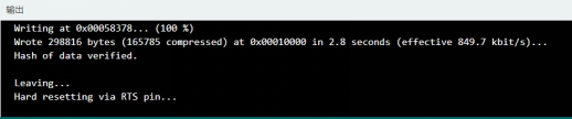
(4) Click “Compile” first, then click “Upload”. After the upload is completed, the program download is completed if the following interface appears in the output box below the software.

11.2.5 Project Outcome
When the controller is in digital mode (only green light on), the robotic arm will not respond to control inputs.
When in analog mode, both red and green lights on, the robotic arm can be controlled. Pressing any button together with SELECT will trigger a predefined motion group. Moving the left joystick left or right will drive the conveyor belt in the corresponding direction, and the more the joystick is pushed, the faster the conveyor moves.
11.2.6 Program Brief Analysis
ino File (Application Layer)
(1) Imports the following libraries: config.h, Hiwonder.hpp, Robot_arm.hpp, PS2_CTL.hpp, and conveyor_belt.hpp. Hiwonder.hpp defines the LED, buzzer, and button objects. Robot_arm.hpp defines the robotic arm object. PS2_CTL.hpp defines the PS2 controller object. conveyor_belt.hpp defines the conveyor belt object.
1 2 3 4 5 | #include "Config.h" #include "Hiwonder.hpp" #include "Robot_arm.hpp" #include "./src/PS2/PS2_CTL.hpp" #include "conveyor_belt.hpp" |
(2) Creates objects for the LED, buzzer, robotic arm, PS2 controller, IIC, and conveyor belt.
7 8 9 10 11 12 | Led_t led_obj; Buzzer_t buzzer_obj; LeArm_t arm; PS2_CTL ps2; IIC iic; CONVEYOR_BELT belt; |
(3) In the setup function, first delay for 1000 ms (1 second), then power off the Bluetooth module. Next, initialize the robotic arm, LED, buzzer, I2C, PS2 controller, and conveyor belt objects, then open the serial port and set the baud rate to 9600.
14 15 16 17 18 19 20 21 22 23 24 25 26 27 28 | void setup() { delay(1000); pinMode(IO_BLE_CTL, OUTPUT); digitalWrite(IO_BLE_CTL, LOW); // Set the Bluetooth control pin to low level to power off the Bluetooth module (设置蓝牙控制引脚为低电平时,断开蓝牙模块电源) arm.init(); led_obj.init(IO_LED); buzzer_obj.init(IO_BUZZER); ps2.init(); iic.init(); belt.init(&iic); Serial.begin(9600); delay(2000); } |
(4) In the main loop, the program enters the ps2_Task function to process controller data.
30 31 32 | void loop() { ps2.PS2_Task(&arm, &led_obj, &buzzer_obj, &belt); } |
PS2_CTL.cpp File (Low-Level)
(1) In the PS2_Task function, the receive_msg method is first called to obtain data sent by the PS2 controller and store it in the button state. Next, the get_result method is called to control the robotic arm based on the button state.
22 23 24 25 26 27 28 29 30 31 32 33 34 35 36 37 38 | void PS2_CTL::PS2_Task(LeArm_t* robot,Led_t* led,Buzzer_t* buzzer,int* stepper_run) { static uint8_t first_flag = 1; if(first_flag!=0) { first_flag = 0; if(mode_count == PS2_SINGLE_SERVO_MODE) { led->blink(250,250,0); }else{ led->blink(250,0,0); } } receive_msg(); get_result(robot,led,buzzer,stepper_run); delay(20); } |
(2) In the receive_msg function, which handles data retrieval and unpacking, the length of the received data is first checked. If the length is not zero, it indicates that data has been received, and the unpacking process begins. Using a state machine, the function first identifies the frame header, then extracts the data length from the frame, and finally starts retrieving the data content.
48 49 50 51 52 53 54 55 56 57 58 59 60 61 62 63 64 65 66 67 68 69 70 71 72 73 74 75 76 77 78 79 80 | void PS2_CTL::receive_msg(void) { static uint8_t step = 0; static uint8_t index = 0; while (Serial_PS2.available()>0) { switch(step){ case 0:{ if(Serial_PS2.read() == FRAME_HEADER) { step++; } }break; case 1:{ if(Serial_PS2.read() == FRAME_HEADER) { index = 0; step++; }else{ step = 0; } }break; case 2:{ recbuff[index++] = Serial_PS2.read(); if(index > 9) { rec_flag = true; step = 0; } }break; default:{ step = 0; }break; } |
(3) First, the mode of the PS2 controller is determined by checking bytes 6 to 9 in the buffer. It identifies whether the controller is in digital mode (PS2_SINGLE_SERVO_MODE) or analog mode (PS2_COORDINATE_MODE).
82 83 84 85 86 87 88 89 90 91 92 93 | if(rec_flag) { if(recbuff[9] == 0x80 && recbuff[6] == 0x80 && recbuff[7] == 0x80 && recbuff[8] == 0x80) { keyvalue.mode = PS2_SINGLE_SERVO_MODE; } else if(recbuff[9] == 0x7F && recbuff[6] == 0x7F && recbuff[7] == 0x7F && recbuff[8] == 0x7F) { keyvalue.mode = PS2_COORDINATE_MODE; } |
(4) Then, based on the detected PS2 mode, different assignment logics are executed accordingly. If the controller is in digital mode, the function reads bytes 3 to 7 from the data buffer to determine the states of buttons such as triangle, circle, up, down, left, right, as well as whether the joysticks have been pressed.
94 95 96 97 98 99 100 101 102 103 104 105 106 107 108 109 110 111 112 | switch(keyvalue.mode){ case PS2_SINGLE_SERVO_MODE: keyvalue.bit_triangle = recbuff[3] & 0xFF; keyvalue.bit_circle = (recbuff[3] & 0xFF) >> 1; keyvalue.bit_cross = (recbuff[3] & 0xFF) >> 2; keyvalue.bit_square = (recbuff[3] & 0xFF) >> 3; keyvalue.bit_l1 = (recbuff[3] & 0xFF) >> 4; keyvalue.bit_r1 = (recbuff[3] & 0xFF) >> 5; keyvalue.bit_l2 = (recbuff[3] & 0xFF) >> 6; keyvalue.bit_r2 = (recbuff[3] & 0xFF) >> 7; keyvalue.bit_select = recbuff[4] & 0xFF; keyvalue.bit_start = (recbuff[4] & 0xFF) >> 1; keyvalue.bit_leftjoystick_press = (recbuff[4] & 0xFF) >> 2; keyvalue.bit_rightjoystick_press = (recbuff[4] & 0xFF) >> 3; keyvalue.bit_left = recbuff[6] == 0x00 ? 1 : 0; keyvalue.bit_right = recbuff[6] == 0xFF ? 1 : 0; keyvalue.bit_up = recbuff[7] == 0x00 ? 1 : 0; keyvalue.bit_down = recbuff[7] == 0xFF ? 1 : 0; break; |
(5) If the controller is in analog mode, it reads bytes 3–4 and 6–9 to get the states of the same buttons and joystick presses, while also retrieving the movement values of the left and right joysticks. These values are assigned to the X and Y positions of the left and right joysticks respectively.
114 115 116 117 118 119 120 121 122 123 124 125 126 127 128 129 130 | case PS2_COORDINATE_MODE: keyvalue.bit_triangle = recbuff[3] & 0xFF; keyvalue.bit_circle = (recbuff[3] & 0xFF) >> 1; keyvalue.bit_cross = (recbuff[3] & 0xFF) >> 2; keyvalue.bit_square = (recbuff[3] & 0xFF) >> 3; keyvalue.bit_l1 = (recbuff[3] & 0xFF) >> 4; keyvalue.bit_r1 = (recbuff[3] & 0xFF) >> 5; keyvalue.bit_l2 = (recbuff[3] & 0xFF) >> 6; keyvalue.bit_r2 = (recbuff[3] & 0xFF) >> 7; keyvalue.bit_select = recbuff[4] & 0xFF; keyvalue.bit_start = (recbuff[4] & 0xFF) >> 1; keyvalue.bit_leftjoystick_press = (recbuff[4] & 0xFF) >> 2; keyvalue.bit_rightjoystick_press = (recbuff[4] & 0xFF) >> 3; keyvalue.left_joystick_x = recbuff[6]; keyvalue.left_joystick_y = recbuff[7]; keyvalue.right_joystick_x = recbuff[8]; keyvalue.right_joystick_y = recbuff[9]; |
(6) Then, based on byte 5, the function updates the status of the directional buttons: bit_up, bit_right, bit_down, and bit_left.
131 132 133 134 135 136 137 138 139 140 141 142 143 144 145 146 147 148 149 150 151 152 153 154 155 156 157 158 159 160 161 162 163 164 165 166 167 168 169 170 171 172 173 174 175 | switch(recbuff[5]) { case 0x00: keyvalue.bit_up = 1; break; case 0x01: keyvalue.bit_up = 1; keyvalue.bit_right = 1; break; case 0x02: keyvalue.bit_right = 1; break; case 0x03: keyvalue.bit_down = 1; keyvalue.bit_right = 1; break; case 0x04: keyvalue.bit_down = 1; break; case 0x05: keyvalue.bit_down = 1; keyvalue.bit_left = 1; break; case 0x06: keyvalue.bit_left = 1; break; case 0x07: keyvalue.bit_up = 1; keyvalue.bit_left = 1; break; case 0x0F: keyvalue.bit_up = 0; keyvalue.bit_down = 0; keyvalue.bit_left = 0; keyvalue.bit_right = 0; break; } |
(7) Once the data has been fully processed, the get_result function uses the button states to control the robotic arm and the conveyor belt, triggering the appropriate actions.
The logic specific to controlling the conveyor belt with the controller is as follows: At the end of each call to get_result, the current X-axis position of the left joystick ranging from 0 on the far left, 127 at center, to 255 on the far right is read. This value is mapped to the conveyor belt speed.
The direction of motion matches the direction the joystick is pushed. The farther the joystick is pushed from the center, the faster the conveyor moves.
Finally, the mapped speed value is passed to the set_speed method of the conveyor belt object, which sends the speed command to the motor driver board via the I2C interface.
11.3 Dual-Arm Cooperative Handling
11.3.1 Project Introduction
In this lesson, two robotic arms work together with a conveyor belt to perform object picking, handling, and sorting.
11.3.2 Project Process
11.3.3 Module Instruction
WonderMV Vision Module
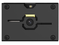
The WonderMV module is equipped with a high-performance K210 chip and supports various AI vision functions such as color recognition, face detection, and identification through programming. This module features an IIC interface, making it easy to connect and exchange data with different controllers, providing an efficient solution for intelligent vision applications.
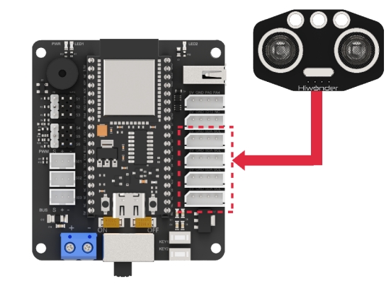
Module connection: As shown in the figure below, please connect the module to any IIC port marked in the red frame on the servo control board before starting the feature.

Ultrasonic Module
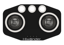
This module uses an IIC communication interface and can read distance measurements from the ultrasonic sensor via IIC. Additionally, the ultrasonic probe integrates two RGB LEDs, which not only support brightness adjustment but also can produce colorful lighting effects through changes and combinations of the red (R), green (G), and blue (B) channels.
Module connection: As shown in the figure below, please connect the module to any IIC port marked in the red frame on the servo control board before starting the feature.
11.3.4 Program Download
WonderMV Program Download
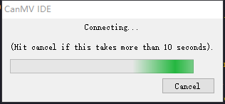
(1) Double-click to open the CanMV IDE development software, and click the connect button in the lower left corner.

(2) Select the corresponding port number, check Advanced Settings, and choose Mode-3.
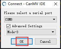
(3) Click OK and wait for the connection.
(4) Once connected successfully, the icon in the lower left corner of the CanMV IDE will appear as shown below.

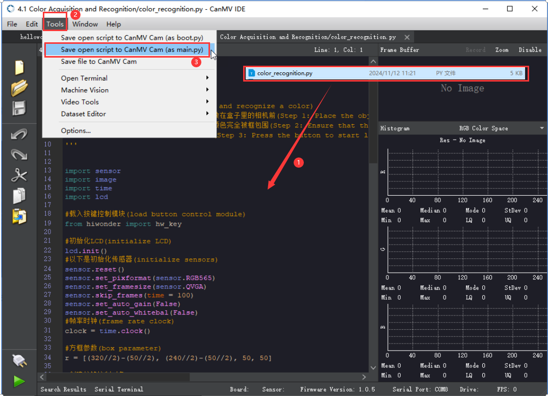
(5) Drag the program file from the same directory of this lesson into the code editor area of CanMV IDE. Click Tools in the toolbar, then select Save the currently opened script as (main.py) to CanMV Cam, as shown below.
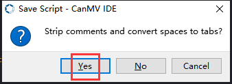
(6) Next, click Yes.
(7) When the write process is successful, a prompt will appear, then click OK. Through above steps to save the MicroPython file to the K210 vision module.

ESP32 Program Download
(1) Connect the core board to the computer using a USB cable.

(2) Locate the corresponding Arduino project file in the same directory as this document.
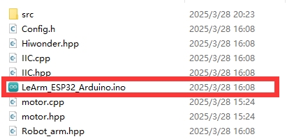
(3) Select the development board model when you open the program, and the specific model is shown in the figure below.

(4) Click “Compile” first, then click “Upload”. After the upload is completed, the program download is completed if the following interface appears in the output box below the software.
11.3.5 Project Outcome
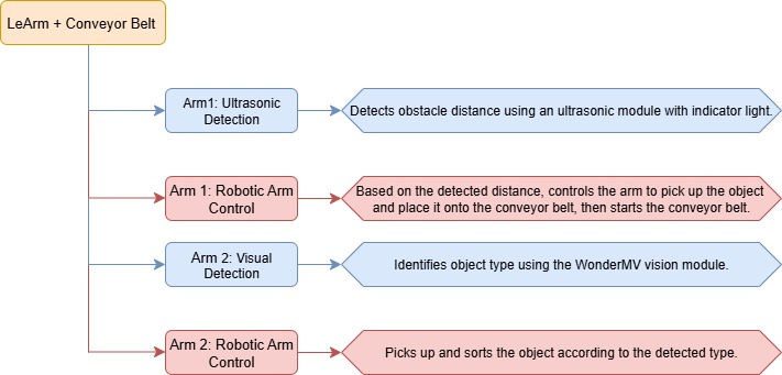
When the ultrasonic module on Arm 1 detects an object, it picks up the object and places it onto the conveyor belt. After running for a certain period, the conveyor belt stops. Then, the vision module on Arm 2 identifies the type of object, and Arm 2 picks it up and sorts it into different locations.
11.3.6 Program Brief Analysis
Arm 1 (Pick and Place onto the Conveyor Belt)
(1) Imports the following libraries: config.h, Hiwonder.hpp, Robot_arm.hpp, IIC.hpp, Ultrasound.hpp, and conveyor_belt.hpp. Hiwonder.hpp defines the LED, buzzer, and button objects. Robot_arm.hpp defines the robotic arm object. IIC.hpp defines the iic object. Ultrasound.hpp defines the ultrasonic sensor object. conveyor_belt.hpp defines the conveyor belt object.
1 2 3 4 5 6 | #include "Config.h" #include "Hiwonder.hpp" #include "Robot_arm.hpp" #include "IIC.hpp" #include "Ultrasound.hpp" #include "conveyor_belt.hpp" |
(2) Create the LED, buzzer, button, robotic arm, IIC, conveyor belt, and ultrasonic sensor objects, and then set the ultrasonic sensor’s compensation value to 10.0.
8 9 10 11 12 13 14 15 | Led_t led_obj; Buzzer_t buzzer; LeArm_t arm; IIC iic; CONVEYOR_BELT belt; Ultrasound ult; #define ULTRASOUND_OFFSET 10.0f |
(3) In the setup function, first delay for 1000 ms (1 second), then power off the Bluetooth module. Next, initialize the robotic arm, LED, buzzer, IIC, vision module, ultrasonic sensor, and conveyor belt objects, then open the serial port and set the baud rate to 9600.
17 18 19 20 21 22 23 24 25 26 27 28 29 30 31 | void setup() { delay(1000); pinMode(IO_BLE_CTL, OUTPUT); digitalWrite(IO_BLE_CTL, LOW); // Set the Bluetooth control pin to low level to power off the Bluetooth module (设置蓝牙控制引脚为低电平时,断开蓝牙模块电源) arm.init(); led_obj.init(IO_LED); buzzer.init(IO_BUZZER); iic.init(); belt.init(&iic); ult.init(&iic); Serial.begin(9600); delay(2000); } |
(4) Then, create a status flag variable.
33 34 | uint8_t running_state = 0; uint8_t finish_count = 0; |
(5) In the main loop, first call the GetDistance method of the ultrasonic sensor object to obtain the measured distance and assign it to the dis variable. Then, based on the value of running_state, execute different business logic.
35 36 37 38 39 40 41 42 43 44 45 46 47 48 49 50 51 52 53 54 55 56 57 58 59 60 61 62 63 64 65 66 67 68 69 70 71 72 73 74 75 76 77 78 79 80 81 82 83 | void loop() { uint16_t dis = ult.GetDistance(); switch(running_state) { case 0:{ if(dis >= 50 && dis <= 100) { delay(1500); dis = ult.GetDistance(); if(dis >= 50 && dis <= 100) { buzzer.blink(1500 , 100 , 100 , 1); arm.coordinate_set((float)(dis / 10) + ULTRASOUND_OFFSET, 0, -7, 0, -90, 90, 1000); delay(1200); running_state = 1; } } delay(100); }break; case 1:{ // Pick (抓取) arm.claw_set(30, 500); delay(700); running_state = 2; }break; case 2:{ // Transition position (过渡位置) arm.coordinate_set(15.0f, 0, 15, 0, -90, 90, 900); delay(900); running_state = 3; }break; case 3:{ // Place (放置) arm.coordinate_set(2.0f, -15, 10, 0, -90, 90, 1000); delay(1000); arm.coordinate_set(2.0f, -15, 1, 0, -90, 90, 800); delay(1000); arm.claw_set(90, 0); delay(500); running_state = 4; }break; case 4:{ arm.coordinate_set(2.0f, -15, 10, 0, -90, 90, 800); delay(1000); belt.set_speed(-100); arm.coordinate_set(15.0f, 0, 15, 0, -90, 90, 1000); delay(7000); // Wait for conveyor to run (等待传送带运行) belt.set_speed(0); running_state = 0; }break; } } |
(6) If the current motion state is 0, the robotic arm remains in the initial position, detecting objects in front:
① First, check whether the measured distance dis is within the range [50, 100]. If not, exit directly. If it is within the range, wait for a short period and then call the GetDistance method of the ultrasonic sensor object again to retrieve the distance value to prevent false triggering.
② If the distance is still within [50, 100], it confirms that there is an object that needs to be picked up. Then, call the blink method of the buzzer object to make it beep at 1500 Hz for 100 ms, pause for 100 ms, and repeat this cycle once.
③ Finally, based on the obstacle distance obtained from the ultrasonic sensor, dynamically calculate the arm movement distance using kinematic analysis and control the robotic arm accordingly. Call the joint control function to move the robotic arm to the object’s position, then switch to the next state.
39 40 41 42 43 44 45 46 47 48 49 50 51 52 53 | case 0:{ if(dis >= 50 && dis <= 100) { delay(1500); dis = ult.GetDistance(); if(dis >= 50 && dis <= 100) { buzzer.blink(1500 , 100 , 100 , 1); arm.coordinate_set((float)(dis / 10) + ULTRASOUND_OFFSET, 0, -7, 0, -90, 90, 1000); delay(1200); running_state = 1; } } delay(100); }break; |
(7) If the current motion state is 1, the robotic arm has detected the object and has moved to its position, then call the joint control function to grip the block. Next, wait for a short period to ensure the gripping is completed, and switch to the next motion state.
54 55 56 57 58 | case 1:{ // Pick (抓取) arm.claw_set(30, 500); delay(700); running_state = 2; }break; |
(8) If the current motion state is 2, the robotic arm has gripped the block, then call the joint control function to lift the block and move to the transition position, then switch to the next state.
59 60 61 62 63 | case 2:{ // Transition position (过渡位置) arm.coordinate_set(15.0f, 0, 15, 0, -90, 90, 900); delay(900); running_state = 3; }break; |
(9) If the current motion state is 3, the robotic arm has lifted the block, then call the joint control function to place the block onto the conveyor belt, release the gripper, and set down the block. Then, switch to the next state.
64 65 66 67 68 69 70 71 72 | case 3:{ // Place (放置) arm.coordinate_set(2.0f, -15, 10, 0, -90, 90, 1000); delay(1000); arm.coordinate_set(2.0f, -15, 1, 0, -90, 90, 800); delay(1000); arm.claw_set(90, 0); delay(500); running_state = 4; }break; |
(10) If the current motion state is 4, the robotic arm has released the block, call the joint control function to return to the home position. After that, run the conveyor belt for a certain period and then stop it, and finally switch back to the initial state 0.
73 74 75 76 77 78 79 80 81 | case 4:{ arm.coordinate_set(2.0f, -15, 10, 0, -90, 90, 800); delay(1000); belt.set_speed(-100); arm.coordinate_set(15.0f, 0, 15, 0, -90, 90, 1000); delay(7000); // Wait for conveyor to run (等待传送带运行) belt.set_speed(0); running_state = 0; }break; |
Arm 2 (Pick from Conveyor Belt and Sort)
(1) The program imports the following libraries: config.h, Hiwonder.hpp, Robot_arm.hpp, IIC.hpp, WonderMV.hpp, and ASR_module.hpp. Among them, Hiwonder.hpp defines the LED, buzzer, and button objects. Robot_arm.hpp defines the robotic arm object. IIC.hpp defines the IIC object. WonderMV.hpp defines the vision module object. ASR_module.hpp defines the voice interaction object.
1 2 3 4 5 6 | #include "Config.h" #include "Hiwonder.hpp" #include "Robot_arm.hpp" #include "IIC.hpp" #include "WonderMV.hpp" #include "ASR_module.hpp" |
(2) Create the LED, buzzer, button, robotic arm, IIC, vision module, and voice interaction objects for subsequent control.
8 9 10 11 12 13 | Led_t led_obj; Buzzer_t buzzer_obj; LeArm_t arm; IIC iic; WonderMV mv; ASR_MOUDLE asr; |
(3) In the setup() function,
① first delay for 1000 ms (1 second), then power off the Bluetooth module. Next, initialize the robotic arm, LED, buzzer, IIC, vision module, and ultrasonic sensor objects, then open the serial port and set the baud rate to 9600.
② Then, call the coordinate_set and claw_set methods of the robotic arm object to return the arm to its home position and open the gripper.
15 16 17 18 19 20 21 22 23 24 25 26 27 28 29 30 31 | void setup() { delay(1000); pinMode(IO_BLE_CTL, OUTPUT); digitalWrite(IO_BLE_CTL, LOW); // Set the Bluetooth control pin to low to cut off the power supply to the Bluetooth module (设置蓝牙控制引脚为低电平时,断开蓝牙模块电源) arm.init(); led_obj.init(IO_LED); buzzer_obj.init(IO_BUZZER); iic.init(); mv.init(&iic); asr.init(&iic); Serial.begin(9600); arm.coordinate_set(2, -15 , 2 , -90 , -90 , 90 , 1000); delay(2000); arm.claw_set(90 , 100); }paste source code here. |
(4) Next, create status flag and vision result variables.
33 34 | uint8_t step = 0; MV_RESULT_ST result; |
(5) In the main loop, different business logic is executed based on the value of step.
36 37 38 39 40 41 42 43 44 45 46 47 48 49 50 51 52 53 54 55 56 57 58 59 60 61 62 63 64 65 66 67 68 69 70 71 72 73 74 75 76 77 78 79 80 81 82 | void loop() { switch(step){ case 0:{ delay(100); mv.get_result(OBJECT_REG, &result); if(result.id != 0){ delay(4000); arm.coordinate_set(2, -19, -1, 0, -90, 90, 600); delay(800); arm.claw_set(30 , 100); delay(500); arm.coordinate_set(2, -15, 10, 0, -90, 90, 600); delay(800); step = 1; } }break; case 1:{ if(result.id == 1){ arm.coordinate_set(2, 15, -5, 0, -90, 90, 1000); delay(1500); arm.claw_set(90, 100); delay(500); }else if(result.id == 2){ arm.coordinate_set(8, 15, -5, 0, -90, 90, 1000); delay(1500); arm.claw_set(90, 100); delay(500); }else if(result.id == 3){ arm.coordinate_set(15, 15, -5, 0, -90, 90, 1000); delay(1500); arm.claw_set(90, 100); delay(500); }else if(result.id == 4){ arm.coordinate_set(15, 0, -5, 0, -90, 90, 1000); delay(1500); arm.claw_set(90, 100); delay(500); } arm.coordinate_set(2, -15 , 2 , -90 , -90 , 90 , 1000); delay(1500); mv.get_result(OBJECT_REG, &result); //Clear the recognition results detected during the handling process(清空识别搬运过程中识别到的结果) result.id = 0; step = 0; }break; default:break; } } |
(6) The program first enters the case 0 branch, where the get_result method of the vision MV object is called to obtain the detected block type, and the color data is stored in result. Then, result.id is checked. If it is not 0, indicating an object has been detected, the robotic arm is controlled to move to the object’s position, close the gripper to pick up the object, and lift it. The program then jumps to the next branch.
38 39 40 41 42 43 44 45 46 47 48 49 50 51 | case 0:{ delay(100); mv.get_result(OBJECT_REG, &result); if(result.id != 0){ delay(4000); arm.coordinate_set(2, -19, -1, 0, -90, 90, 600); delay(800); arm.claw_set(30 , 100); delay(500); arm.coordinate_set(2, -15, 10, 0, -90, 90, 600); delay(800); step = 1; } }break; |
(7) In the case 1 branch, based on the value of result.id (i.e., the detected object type), the robotic arm moves to different trash bins and places the object to complete sorting, then returns to the home position.
52 53 54 55 56 57 58 59 60 61 62 63 64 65 66 67 68 69 70 71 72 73 74 75 76 77 78 79 | case 1:{ if(result.id == 1){ arm.coordinate_set(2, 15, -5, 0, -90, 90, 1000); delay(1500); arm.claw_set(90, 100); delay(500); }else if(result.id == 2){ arm.coordinate_set(8, 15, -5, 0, -90, 90, 1000); delay(1500); arm.claw_set(90, 100); delay(500); }else if(result.id == 3){ arm.coordinate_set(15, 15, -5, 0, -90, 90, 1000); delay(1500); arm.claw_set(90, 100); delay(500); }else if(result.id == 4){ arm.coordinate_set(15, 0, -5, 0, -90, 90, 1000); delay(1500); arm.claw_set(90, 100); delay(500); } arm.coordinate_set(2, -15 , 2 , -90 , -90 , 90 , 1000); delay(1500); mv.get_result(OBJECT_REG, &result); //Clear the recognition results detected during the handling process(清空识别搬运过程中识别到的结果) result.id = 0; step = 0; }break; |