5. Motion Planning and MoveIt Simulation
5.1 Introduction to URDF Model
5.1.1 URDF Model Introduction
The Unified Robotic Description Format(URDF) is an XML file format,universal description format,used in ROS to describe the robot structure.Robots are usually composed of several linkages andjoints that connecttwolinkages.A robot motion model is that multiple linkages are connected andrestricted by each other.And UDRF files describe the relationship betweenjoints and linkages,and their inertial properties,geometric characteristics andcollision models.
5.1.2 Difference between xacro and URDF Model
The URDF model is a straightforward file for describing robot models, but its simplicity can become a drawback when describing more complex robots, leading to lengthy description files that lack conciseness. In contrast, the xacro model is an extension of the URDF model, and it offers a more advanced way of describing robots. By using the xacro format, you can simplify the robot description file, improve the reusability of the code, and solve the verbosity problem of the URDF model. For instance, when describing the legs of a humanoid robot, using the URDF model would require a separate description of each leg. However, with the xacro model, you can describe a single leg and reuse it throughout the robot’s structure. Overall, the xacro model is a powerful tool that can make robot modeling more efficient, flexible, and maintainable. By leveraging its advanced features, you can create complex robot structures with ease and reduce the overhead associated with manual coding.
5.1.3 Install URDF Dependencies
(1) Input command and press Enter to update the package information.
sudo apt update
(2) Input command and press Enter to install URDF model.
sudo apt-get install ros-melodic-urdf
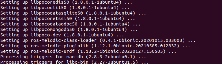
When you receive the following messages, the installation is successful.
(3) Input command and press Enter to install URDF model.
sudo apt-get install ros-melodic-xacro
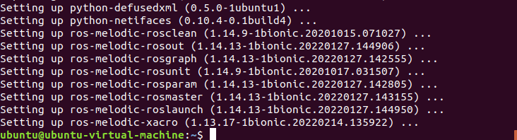
When the hints appear as pictured, the installation is finished.
5.1.4 Basic Syntax of URDF Model
XML Basic Syntax
As the URDF model is written upon XML standard, you need to get a understanding of the basic structure of XML format.
Element:
You can define the element as any name, but you need to adhere to the below format
<element>
</element>
Attribute:
Attribute is included in element, which defines natures and parameters of element. When using attribute to define element, please conform to the below format.
<element
attribute_1 = "attribute value1"
attribute_2 = "attribute valur2">
</element>
Note
to avoid affecting other attributes and elements, please use the below format to comment.
<!-- commented content>
Link
In URDF model, link describes the appearance and physical properties of arigid component. The following tags will be used in editing link action.
<link name="link name">
	<inertial>......</inertial>
    <visual>......</visual>
    <collision>......</collision>
</link>
<visual>:describe the appearance parameters of link, including size, color, shape, etc.
<inertial>:describe inertial parameters of link containing dynamics operation of the robot.
<collision>:describes the collision properties of link.
Each tag has its child tag, and the function of each tag is different. Below is a table of functions of corresponding tags.
| Tag | Function |
|---|---|
| origin | Describe the pose of link. It containstwo parameters, including xyz and rpy.xyz: describe the pose of link on simulation map.rpy: describe the posture of link on simulation map. |
| mess | Describe mass of a link |
| inertia | Describe inertia of a link. Because of the symmetry of inertial matrix, these |
Joint
In URDF, “joint” describes the properties of joint kinematics and dynamics, the position and speed restriction. According to the types of movement, joints can be divided into 6 types.

The following keywords will be adopted to edit joint movements.
<joint name="name of joint">
	<parent link="link1">
    <child link="link2">
    <calibration>......</calibration>
    <dynamics damping ....../>
    <limit effort ....../>
</joint>
<parent_link>: parent link
<child_link>:child link
<calibration>:calibrate joint angle
<dynamics>:describe physical attributes of movement
<limit>:describe limit value of movement
Each tag has its child tag, and the function of each tag is different. Below is a table of functions of corresponding tags.
| Tag | Function |
|---|---|
| origin | Describe the pose of link. It contains two parameters, including xyz and rpy.xyz: describe the pose of link on simulation map.rpy: describe the posture of link on simulation map. |
| axis | Used to control child link to rotate around X, Y or Z axis of parent link |
| limit | It is used to limit child link. Attributes of lower and upper limit rotation range.effort(unit: N) attribute restricts the force range during rotation. velocity attribute limits rotation speed(unit: m/s) |
| mimic | Describe the relationship between this joint and other joints. |
| safety_controller | Describe the parameter of safety controller which can protect joint motion of robot. |
robot Tag
To make top tag of robot complete, <link> and <joint> tags must be involved in <robot>.
<robot name="name of robot">
	<link>......</link>
    <link>......</link>

    <joint>......</joint>
    <joint>......</joint>
</robot>
gazebo Tag
This tag is used with gazebo simulator to set simulation parameters. It can be employed to introduce gazebo plug-ins, physical attributes, etc.
<gazebo reference="link1">
	<material>Gazebo/Black</material>
</gazebo>
Write a Simple URDF Model
(1) Name the Robot Model
Before writing an URDF model, you need to name the model in this format “<robot name=”ABCD “>” . At last, enter “</robot>” to indicate that robot model is written successfully.
<?xml version="1.0"?>
<robot name="pan_tilt">

</robot>
(2) Set a Link
① When writing the first link, indent to sign that this link belongs to the model. Then name this link in this format “<link name=’name’>” . In the end, enter “</link>” to show that you complete writing the link.
<link name="base_link">

</link>
② When writing a link description, use indentation to indicate that the
description is related to the link being set. You need to enter “<visual>” to at the beginning and “</visual>” at the end.
<visual>

</visual>
③ “<geometry>” describes the shape of a link. To end description, input “</geometry>” . Besides, you need to indent to indicate that the indented content is the description of the shape of a link. For instance, the following content is the description of the shape of a link. “length=’0.01’” means that the length of this link is 0.01m, and “radius=’0.2’” indicates that the radius of this link is 0.2m.
<geometry>
	<cylinder length="0.01" radius="0.2" />
</geometry>
④ “<origin>” describes the position of a link. You need to indent to show the description of link position. “<origin rpy=’0 0 0’ xyz=’0 0 0’ />” describes the position of a link. rpy is link angle and xyz is the coordinate of the link. “xyz=’0 0 0’” means that the link is at the origin of the coordinate system.
<origin rpy="0 0 0" xyz="0 0 0" />
⑤ “<material>” describes the appearance of a link. Use indentation to point out the description of the color of a link. “<material>” needs to be input at the beginning of the description and “</material>” at the end. The below codes sets the color of a link as yellow. “<color rgba=’1 1 0 1’ />” ,”rgba=’1 1 0 1’” is the color threshold value.
<material name="yellow">
	<color rgba="1 1 0 1" />
</material>
(3) Set a Joint
① When writing the first link, indent to sign that this link belongs to the model being set. Then name this link and set its type in this format “joint”
name=”ABCD” type=”ABCD”> . In the end, enter “</link>” to show that you
complete writing the link. To learn more about the type of joints, please refer to “5.1.4 Basic Syntax of URDF Model -> Joint” .
<joint name="pan_joint" type="revolute">

</joint>
② When writing joint description, use indent to indicate this description is for
the joint being set. In addition, parameters of parent and child need to be set in these format “<parent link=’ABCD’/>” and “<child link=’ABCD’/>” . Joint will take the parent link as fulcrum to rotate the child link.
<parent link="base_link" />
<child link="pan_link" />
③ “<origin>” describes the position of a joint. You need to use indentation to show the description for link position. “<origin xyz=”0 0 0.1 “/>” describes the position of a link. xyz is the coordinate of a joint.
<origin xyz="0 0 0.1" />
④ “<axis>” describes the position of a link. Use indentation to indicate that the description is related to the link position. The below content “<axis xyz= ‘0 0 1 ‘/>” describes the posture of a joint. xyz is posture position of the joint.
<axis xyz="0 0 1" />
⑤ “<limit>” is used to limit the motion of a joint. When describing a joint, you need to use indentation to this description is related to limitation of joint angle. The below content describes that the force used to rotate joint should not exceed 300N, the upper limit of rotation range is 3.14 radian and lower limit of rotation range is -3.14 radian. You can them in these format “effort=’joint force(N)’ 、velocity=’rotation speed of a joint’ 、lower=’lower limit of rotation range’ 、upper=’upper limit of rotation range’” .
<limit effort="300" velocity="0.1" lower="-3.14" upper="3.14" />
⑥ “<dynamics>” describes dynamics of a joint. When describing dynamics of a joint, use indentation to indicate this description is related to joint posture. “
<dynamics damping="50" friction="1" />
The entire code is shown below:
<?xml version="1.0"?>
<robot name="pan tilt">

	<!--定义Jbase link -->
	<!--<visual>标签描述了在仿真环境的外观,包括几何外形geometry>(园柱形cylinder)等-->
	<link name="base link">
		<visual>
			<geometry>
				<cylinder length="0.01" radius="0.2" />
			</geometry>
			<origin rpy="0 0 0" xyz="0 0 0" />
			<material name="yellow">
				<color rgba="1 1 0 1"/>
			</material>
		</visual>
	</link>

    <!--定义了关节pan joint,以及其关节类型:旋转副(有限制)-->
	<!--旋转副连接的两个刚体分别为base link和pan link -->
	<joint name="pan joint" type="revolute">
		<parent link="base link" />
		<child link="pan link" />
		<origin xyz="0 0 0.1"/>
		<axis xyz="0 0 1" />
		<limit effort="300" velocity="0.1" lower="-3.14" upper="3.14" />
		<dynamics damping="50" friction="1"/>
	</joint>

    <link name="pan_link">
		<visual>
			<geometry>
				<cylinder length="0.4" radius="0.04" />
			</geometry>
			<origin rpy="6 0 θ" xyz="0 0 0.09"/>
			<material name="red">
				<color rgba="6 0 1 1"/>
			</material>
		</visual>
	</link>

    <joint name="tilt joint" type="continuous">
		<parent link="pan link" />
		<child link="tilt link" />
		<origin xyz="0 0 0.2"/>
		<axis xyz="0 1 0" />
		<limit effort="300" velocity="0.1" lower="-4.64" upper="-1.5"/>
		<dynamics damping="50" friction="1"/>
	</joint>

    <link name="tilt link">
		<visual>
			<geometry>
				<cylinder length="0.4" radius="0.04" />
			</geometry>
			<origin rpy="0 1.5 0" xyz="0 0 0" />
			<material name="green">
				<color rgba="1 0 0 1"/>
			</material>
		</visual>
	</link>
</robot>
5.2 ROS Robot URDF Model Description
Note
the input command should be case sensitive, and the keywords can be complemented by Tab key.
5.2.1 View Robotic Arm Model Code
(1) Start ArmPi FPV, then connect it to NoMachine.
(2) Double click  to open the command line terminal.
cd armpi_fpv/src/armpi_fpv_descrption/urdf
(3) Input command, then press Enter to enter the startup program directory.
vim armpi_fpv.urdf
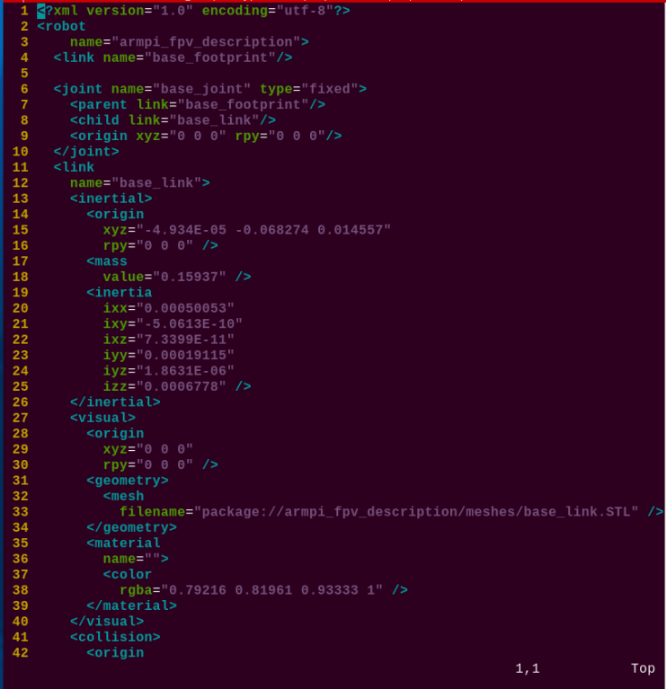
(4) Locate the following codes.
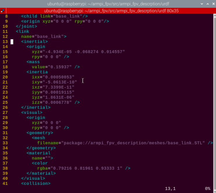
In the above figure, multiple URDF models are called to compose the complete robot arm.
| label | Instruction |
|---|---|
| material | color |
| inertial | Inertia makes the Gazebo physics engine work properly |
| base_link | Robotic arm body model |
| robot | Overall name for URDF files |
| joint | Movable mechanical component, such as, shaft |
5.2.2 ArmPi FPV Model Analysis
Parameters of Each Joints
Robotic arm defines six links in the full code, and each link represents a joint. Since the definition of Link1 to Link5 are roughly the same, only the model and initial position are different, so here is an example of Link:
Describe <inertlal>: define the initial position where the inertial is produced (the keyword is “origin”), define quantity (the keyword is “mass”), define the inertial nature (the keywaord is “inertial”)
Define <visual> to describe appearance: the position is the origin (the keyword is “origin” , import the related model (the keyword is “geometry”). Define the color as blue (the keyword is “material”).
Define <collision>: the initial position where the collision is produced (the keyword is “origin”) and the model of the collision position (the keyword is “geometry”). Define the color as gray (the keyword is material).
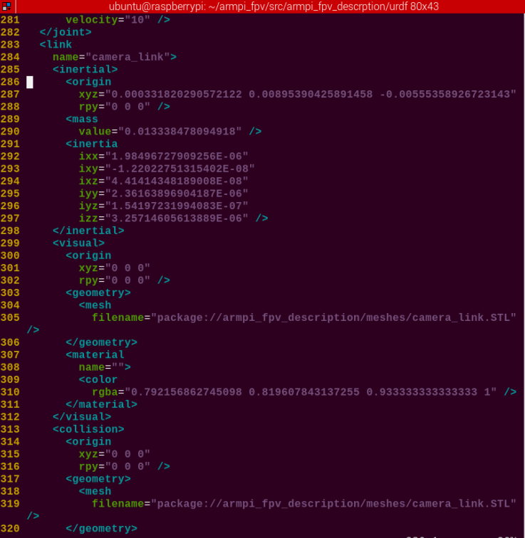
Camera Model Parameter
The camera model is defined with “camera_link” .
Describes its inertia <inertlal>: defines the initial position where the inertia is generated (keyword “origin”), defines the mass (keyword “mass”), defines the inertia properties (keyword “inertia”).
Define <visual> to describe the appearance: define position as origin (keyword “origin”), import the relevant appearance model (keyword “geometry”), define the color as gray (keyword “material”).
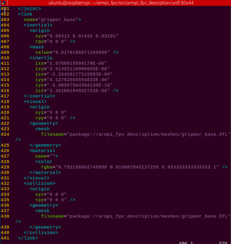
Gripper Parameter
The gripper model is defined with “gripper_base”。
Describes its inertia <inertlal>: defines the initial position (keyword “origin”), defines the mass (keyword “mass”), defines the inertia properties (keyword “ inertia”).
Define <visual> to describe the appearance: position as origin (keyword “origin”), introduce the relevant appearance model (keyword “geometry”), define the color as gray (keyword “material”).
5.3 Set Up Development Environment
Note
Please enter the password “ubuntu” to access the virtual machine.
5.3.1 Build up Environment
Install and Power the Virtual Machine
(1) Prepare a computer and connect it to Wi-Fi.

(2) Extract the Ubuntu image package and virtual machine installation pack
which are saved in the same folder.
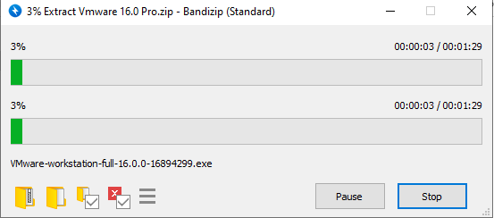
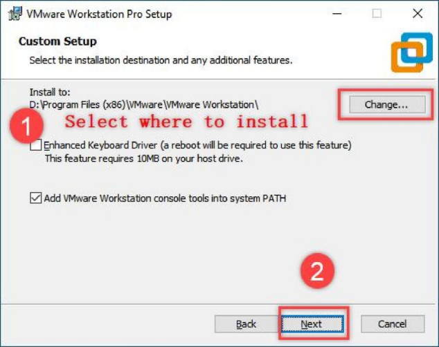
(3) After packages are extracted, double click the .exe file to execute it.

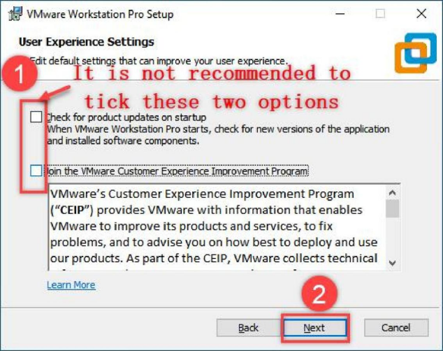
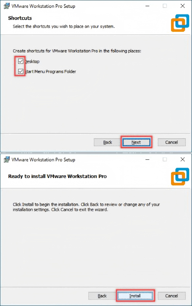
(4) Finish the installation following the instructions.

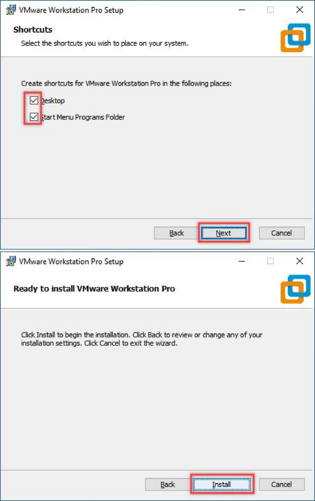

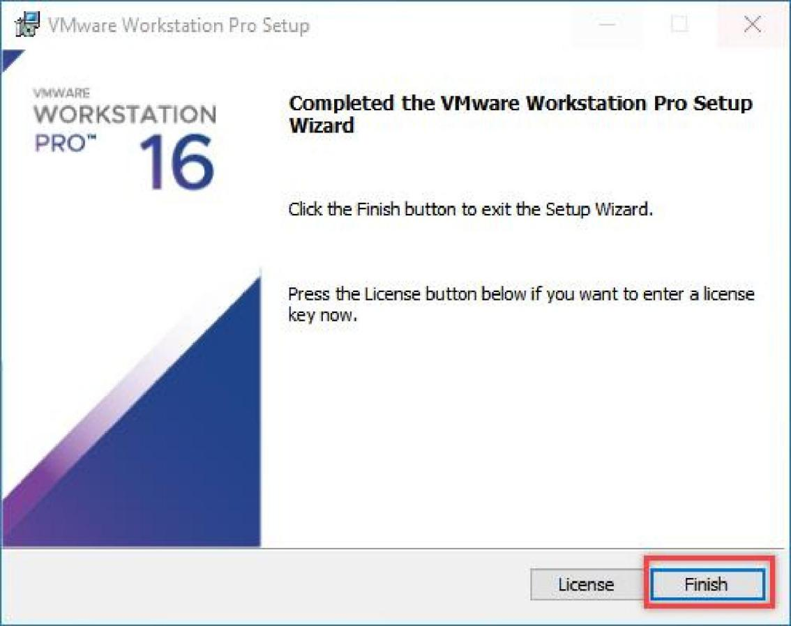
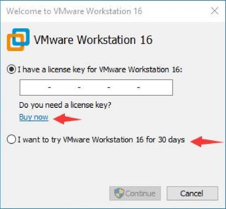
(5) After the software is installed successfully, open it. VMware Workstation offers 30-day free trial. After 30-day trial, you can purchase a license key to activate this software. If you need free resource, please contact us via email.
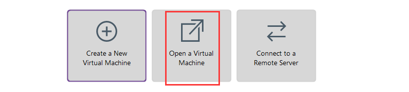
(6) Enter the home interface, then click “Open virtual machine”.
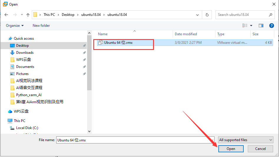
(7) Select the Ubuntu image file “ Ubuntu64位.vmx” , then click “Open”.
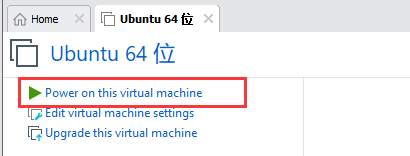
(8) Having completed the above steps, power on this virtual machine.
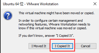
(9) Select “I have copied this virtual machine”.
(10) After the virtual machine is boot, enter the password “ubuntu” to access the system.
5.3.2 Establish Connection
Access the IP of Virtual Machine under Bridge Mode
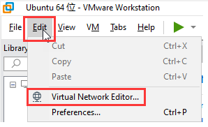
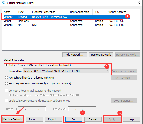
(1) Click “Edit->Network editor”.
(2) Select “VMnet0” , and then select the corresponding network card needed to be bridged to. Following, click “Apply -> OK” in sequence. If it cannot be bridged to “VMnet0” , click “restore default settings” .
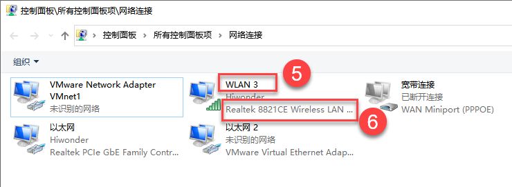
To view the type of the network card, please refer to the below instructions. Take Win10 as an example:
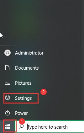
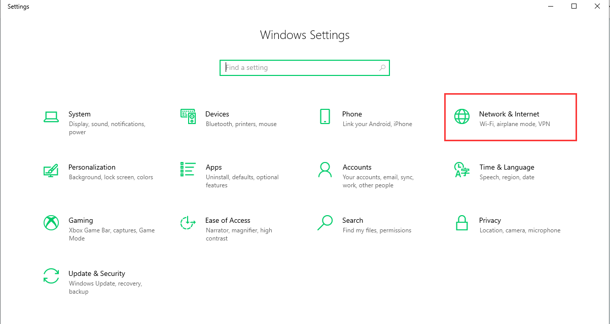
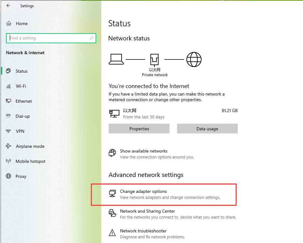
(1) Click “ ->Settings->Network and Internet->Change adaptor option” in sequence. Then you can find the network card type as pictured (Step 5 + 6).
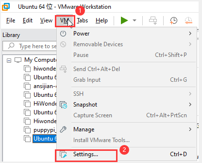
(2) Having completed the previous steps, click “virtual machine -> settings” .
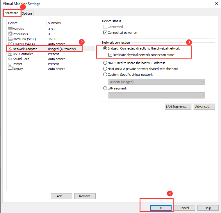
(3) Click on “Hardware -> Network adaptor -> Bridge mode -> Copy physical network connection status -> OK” to configure the virtual machine network.
(4) Open ubuntu command-line terminal. Input the command “ifconfig” to check the IP of virtual machine, and remember to record it.
ifconfig
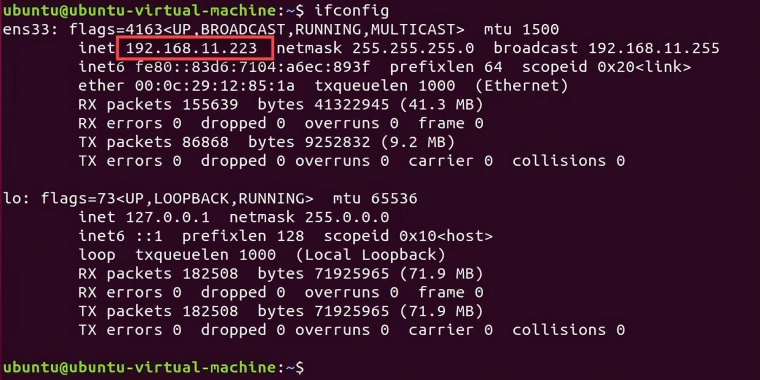
Note
if the IP doesn’t show up after you input the command “ifconfig”, please wait for a while, then enter the command again.
Access Robot Arm IP
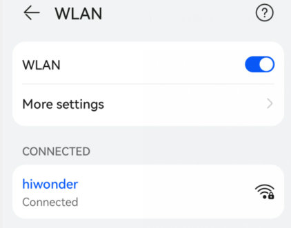
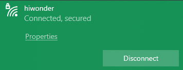
(1) Connect your phone to the same Wi-Fi as your computer, for example “Hiwonder”.
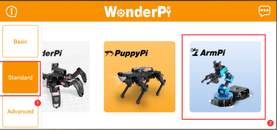
(2) Click-on “Advanced -> ArmPi” .
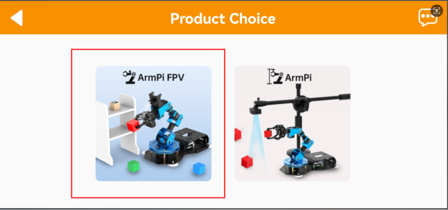
(3) Select “ArmPi FPV”.
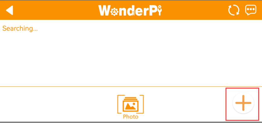
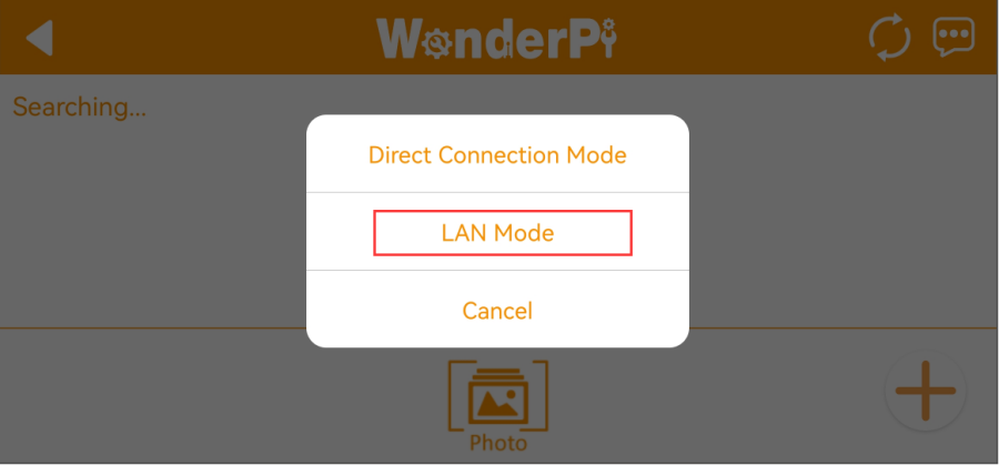
(4) Click on “+” button and select “ LAN mode” .
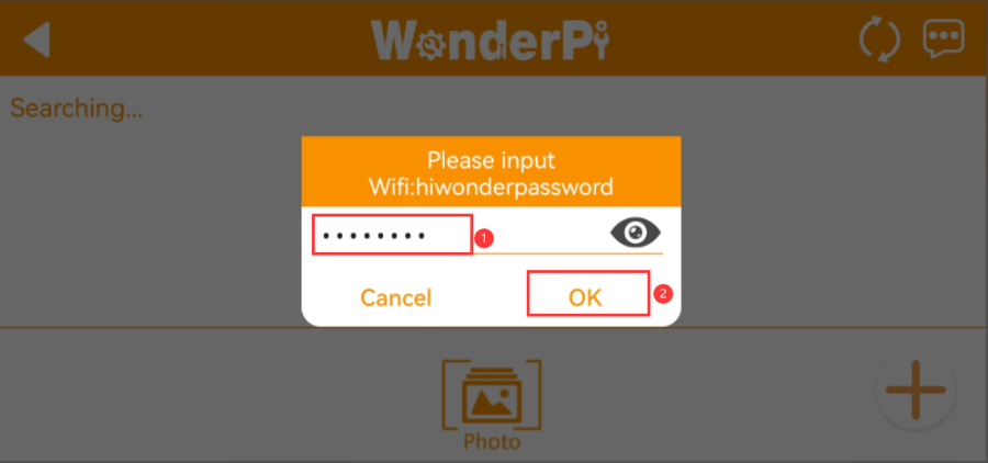
(5) Input the password of the Wi-Fi, then click “OK” .

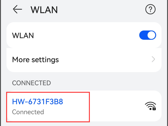
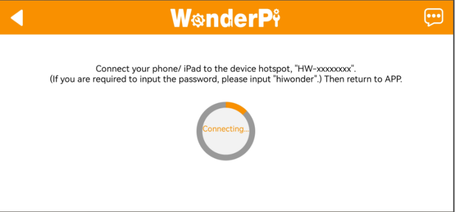
(6) Click “Go to connect device hotspot” . The device hotspot usually starts with the letter “ HW” .
(7) Wait for the app to connect to the Wi-Fi.
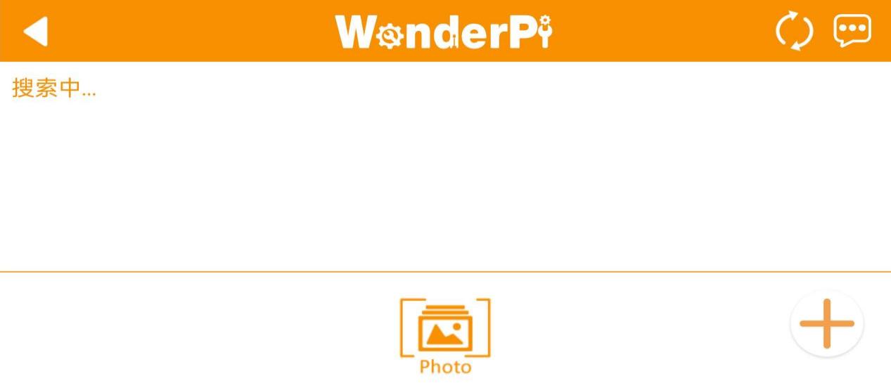
(8) The app will pair with the robot automatically. If no robot is matched, please click on  to search the device again.
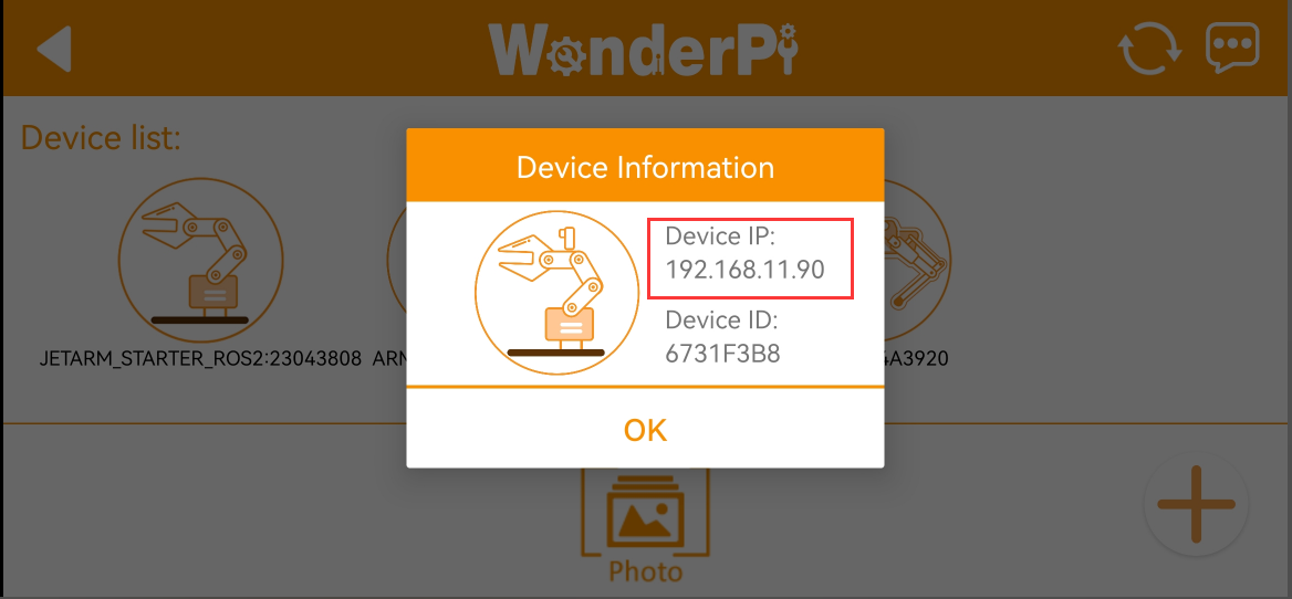
(9) When the robot is connected, press the robotic button to get the device’s IP address and take it down.
Add Virtual Machine’s IP
(1) Please confirm that computer and phone are connected to the same Wi-Fi.
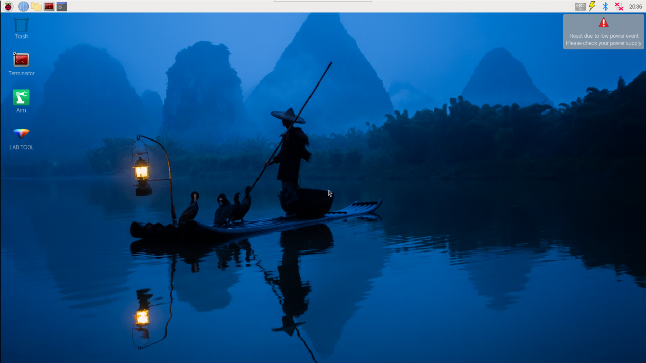
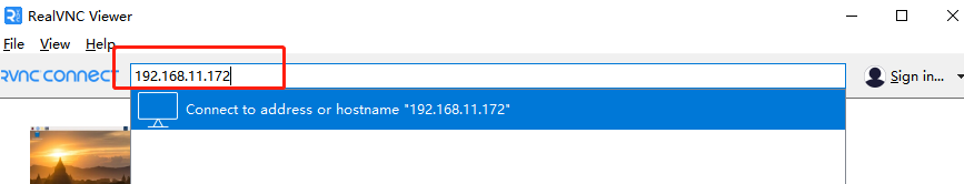
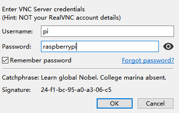
(2) Once the connection is complete, double-click  and enter the device IP obtained in “Access Robot Arm IP” in the location sho wn in the image below, then click the green box.
(3) Next, enter the username “pi” and the password “raspberrypi” as shown in the image to access the device desktop.
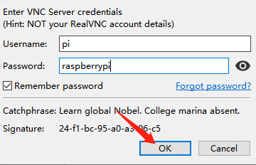
(4) Choose ‘OK’.
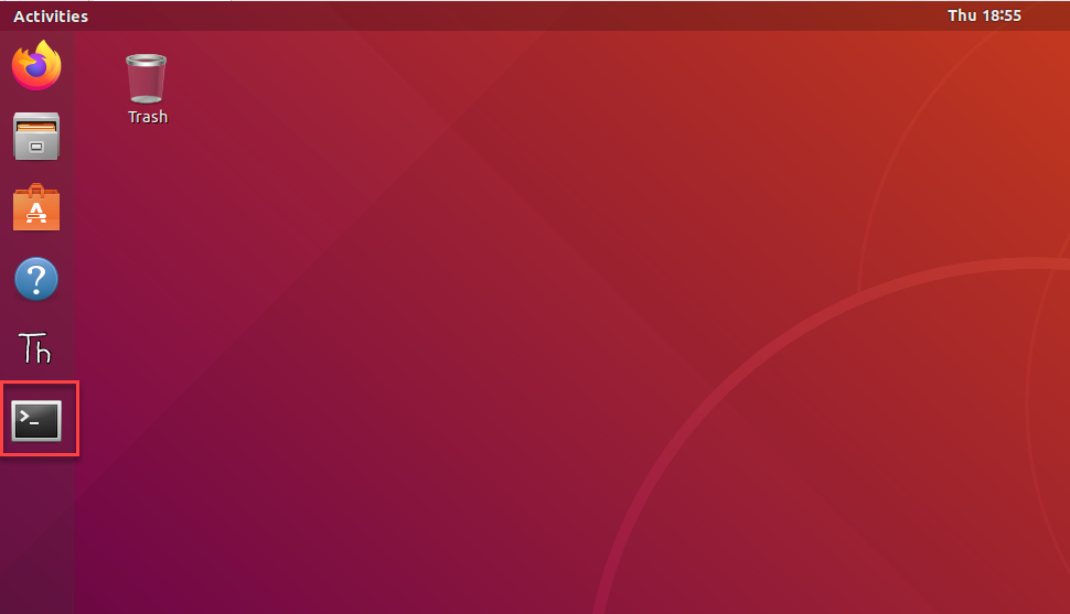
(5) Click-on  to open the command-line terminal.
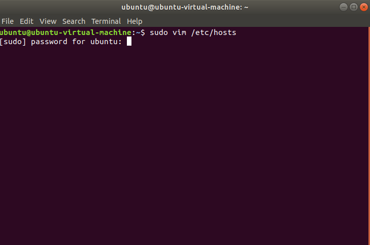
(6) Enter the following command and press Enter to access the network configuration file:
sudo vim /etc/hosts
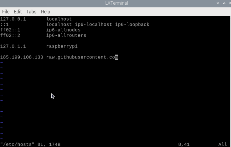
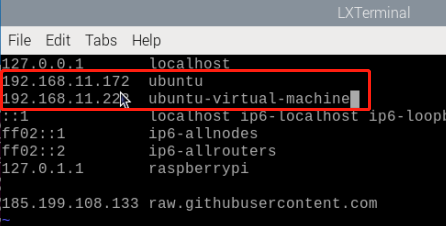
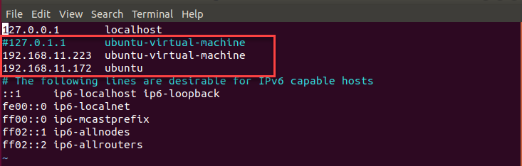
(7) Press the “i” key to enter editing mode, and add the robotic arm’s IP address and the virtual machine’s IP address below the second line. (Note: Do not change the name following the IP address.)
(8) Press the “Esc” key, then enter the following command to exit and save:
:wq
Add the IP to Virtual Machine
(1) Click-on  to open the command–line terminal.
(2) Input the command and press Enter to open the network configuration file. If you are required to enter the password, enter “ubuntu” .
sudo vim /etc/hosts
(3) Press “i” to enter the editing mode, then comment 2nd line and add the IP of robot arm and virtual machine under 2nd line.
(4) Press “Esc” and input “:wq” to save and exit the file.
:wq
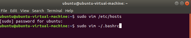
(5) Input the command “sudo vim ~/.bashrc” and press Enter to open the network configuration file. If you are required to enter the password, enter “ubuntu” . NOTE: the entered password will be hidden. When the password is complete, press Enter key.
sudo vim ~/.bashrc
(6) Press “i” key to enter the editing mode, and then change the last two lines “ROS_MASTER_URI” to “http://+IP address of robot arm+:11311”. In addition, modify “ROS_HOSTNAME” as the IP address of virtual machine.
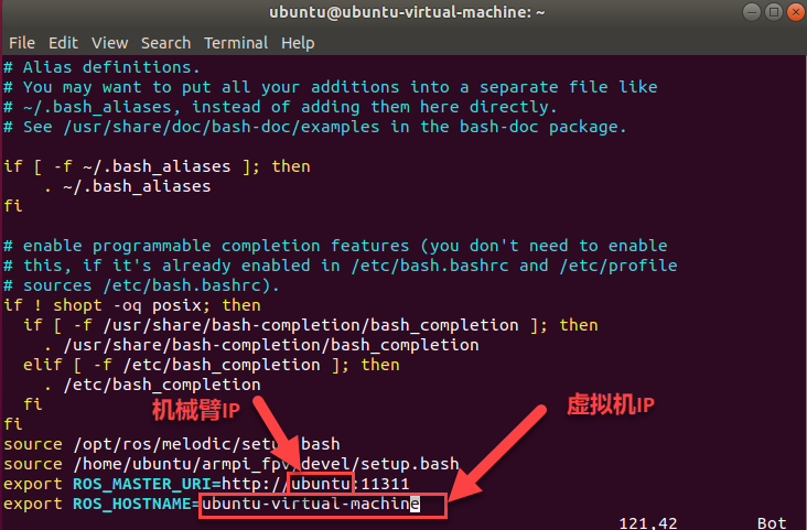

(7) Press “Esc” and enter “:wq” to save and exit the file.
:wq
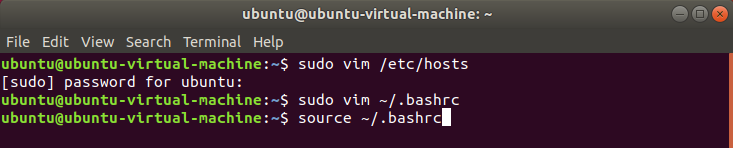
(8) Enter the command “source ~/.bashrc” on Ubuntu command-line terminal to validate the changes.
source ~/.bashrc
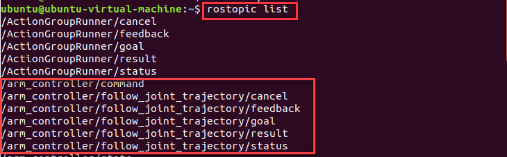
(9) Enter the command “rostopic list” . If the nodes of ArmPi FPV are enabled, that means that network is configured successfully.
rostopic list
5.3.3 MoveIt Configuration
Note
MoveIt has been configured so you do not need to modify and can use it directly. This lesson is an introduction to the configuration.
MoveIt Introduction
MoveIt is composed of a series of functional packages for motion control in ROS, including motion planing, manipulation, 3D perception, kinematics and collision checking. It is currently the most advanced software for mobile operations.
It provides an easy-to-use platform for developing advanced robot application, evaluating robotics design and building integrated robots, and is the most widely used open-source software for industrial, commercial, and research use. In addition, MoveIt also provides a series of plug-ins and tools to realize rapid configuration of robotic arm control, and encapsulates a large number of APIs to facilitate secondary development on the MoveIt module, and thus develop more creative applications.
Enable Configuration Program
Note
the entered command should be case sensitive and “Tab” key can be used to complement the key words.
(1) Start ArmPi FPV, and connect it with virtual machine.
(2) Double click on  to open terminal.
(3) Open a new terminal and input command and press Enter to start MoveIt.
roslaunch armpi_fpv_moveit_config setup_assistant.launch
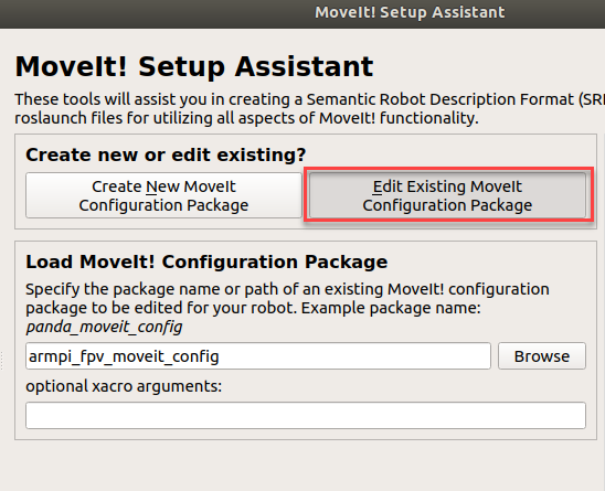
(4) Click “Edit Existing MoveIt Configuration Package” to edit the existing configuration package.
Edit Existing MoveIt Configuration Package
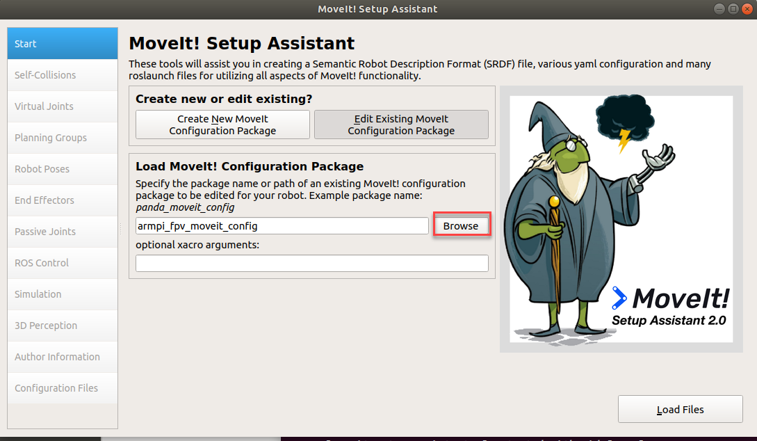
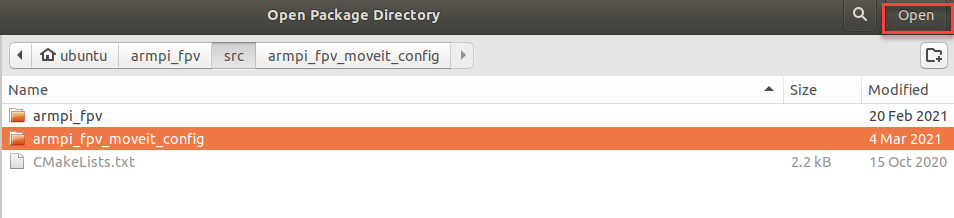
(5) Then click “Browse” . Select and open the folder “armpi_fpv_moveit_config” in “/home/ubuntu/armpi_fpv/src”.
(6) Click “Load Files”.
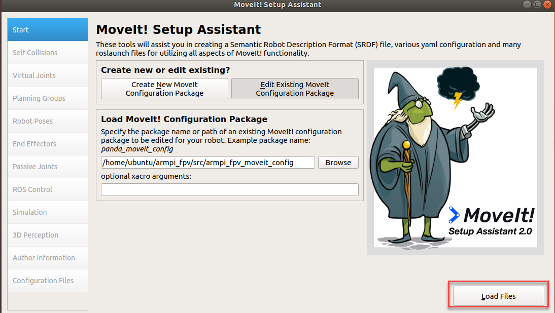
When the process bar turns to 100%, the robot model will appear at right, it indicates the loading is complete.

(7) Then configure “Virtual joints” and “ Robot pose” at left.
Note
the new settings will replace the previous one. If part of steps get wrong, the software can not be used.
Configuration Introduction
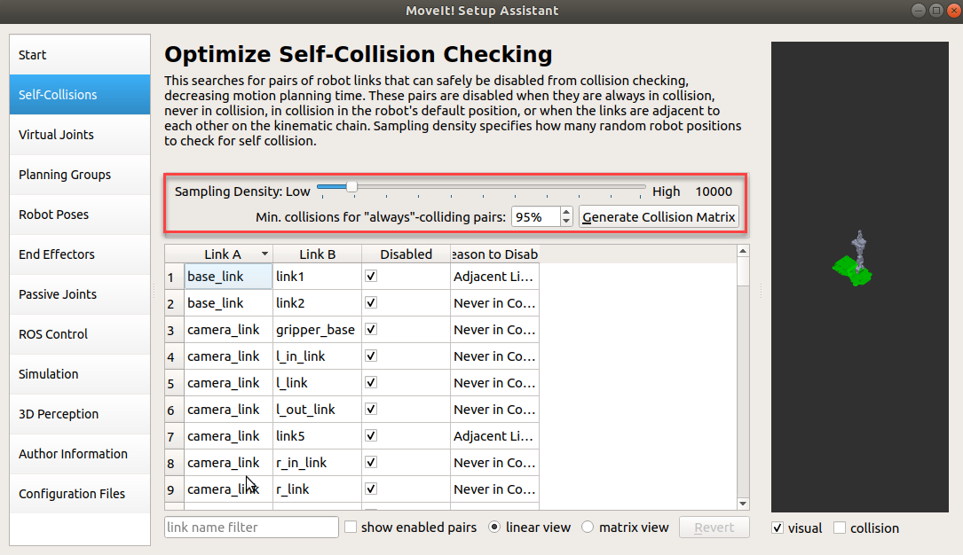
(1) Self-Collisions
Generate the customized collision matrix. The default collision matrix generator can search all the joints of robot, but this collision matrix can safely be disabled from collision checking, decreasing motion planing time.
Sampling density specifies how many random robot positions to check for self collision. A higher density requires more computation time, with a default value of 10,000 collision checking.
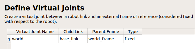
(2) Virtual joints
Add virtual joints. Virtual joint is primarily used to connect robot to simulation program. In the following example, a virtual joint is defined to connect base_footprint and world_frame frameworks.
(3) Planning Groups
Add joint group. It is primarily used to describe different joints required to build a robot.

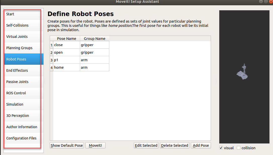
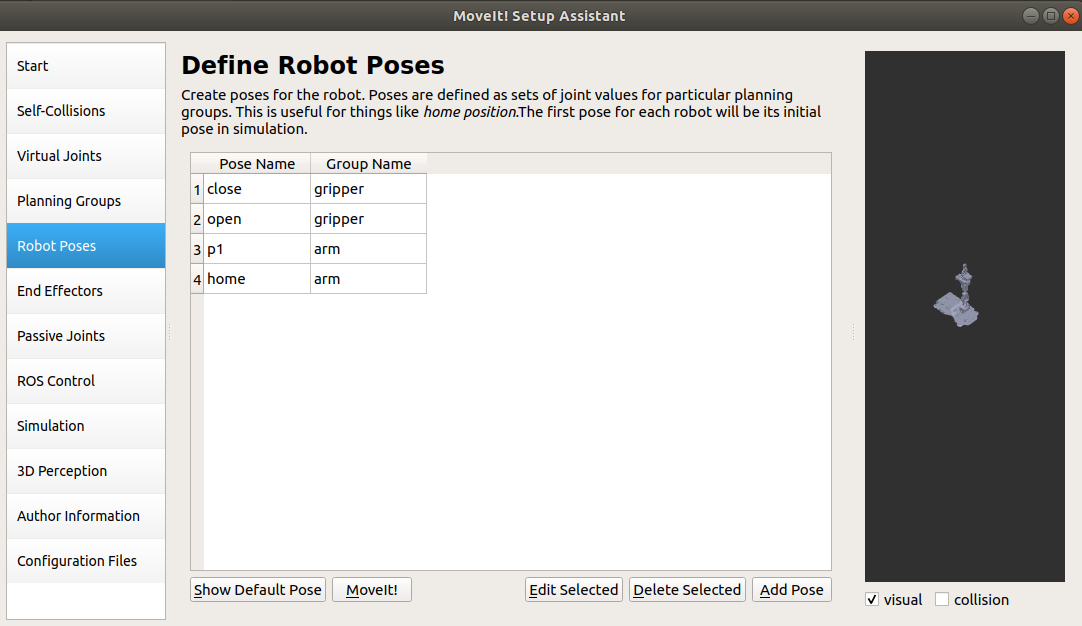
(4) Robot Poses
Define the pose of the robot, customize the name of the robot’s pose, and the joint combinations required for that pose.
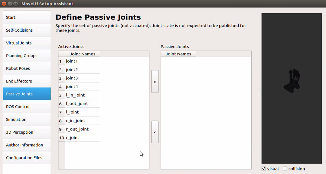
(5) Passive Joints
Specify the set of passive joints (not actuated). Joint state is not expected to be published for these joints.
(6) ROS Control
Simulation controller is added via ROS control panel, thus we can use MoveIt to simulate robot’s motion.

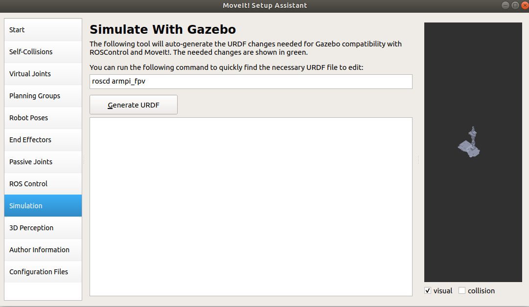
(7) Simulation
Set up the URDF file needed for Gazebo simulation.
(8) 3D perception
① Environment perception
Support external sensor. It is capable of converting the captured point cloud or deep data into octomap and add them to the simulation environment for motion planning and obstacle avoidance.

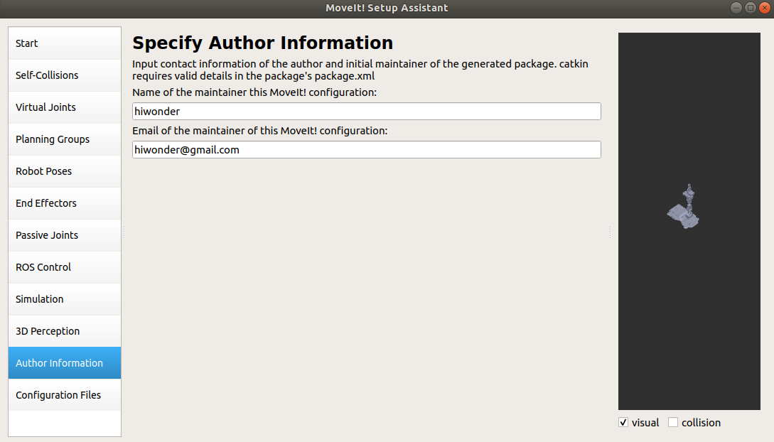
(9) Author Information
Add author information.
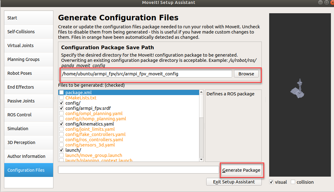
(10) Configuration Files
Generate the configuration file. After confirming the file path, click “Generate Package”.
5.4 Movelt Usage Precaution and Control
5.4.1 Usage Precaution
Place the robot in a wide area to ensure enough motion space. Keep a certain distance from the robot to avoid hurt when robot is working. In following operations, MoveIt is used to plan the path so that control simulation model and real robot to move to specific position.
5.4.2 Enable Related Service
Note
the input command should be case sensitive, and keywords can be complemented by “Tab” key.
(1) Start ArmPi FPV, and connect it to NoMachine.
(2) Double click  to open terminal.
(3) Open another new terminal and enter command and press Enter to enable MoveIt tool.
roslaunch armpi_fpv_moveit_config demo.launch
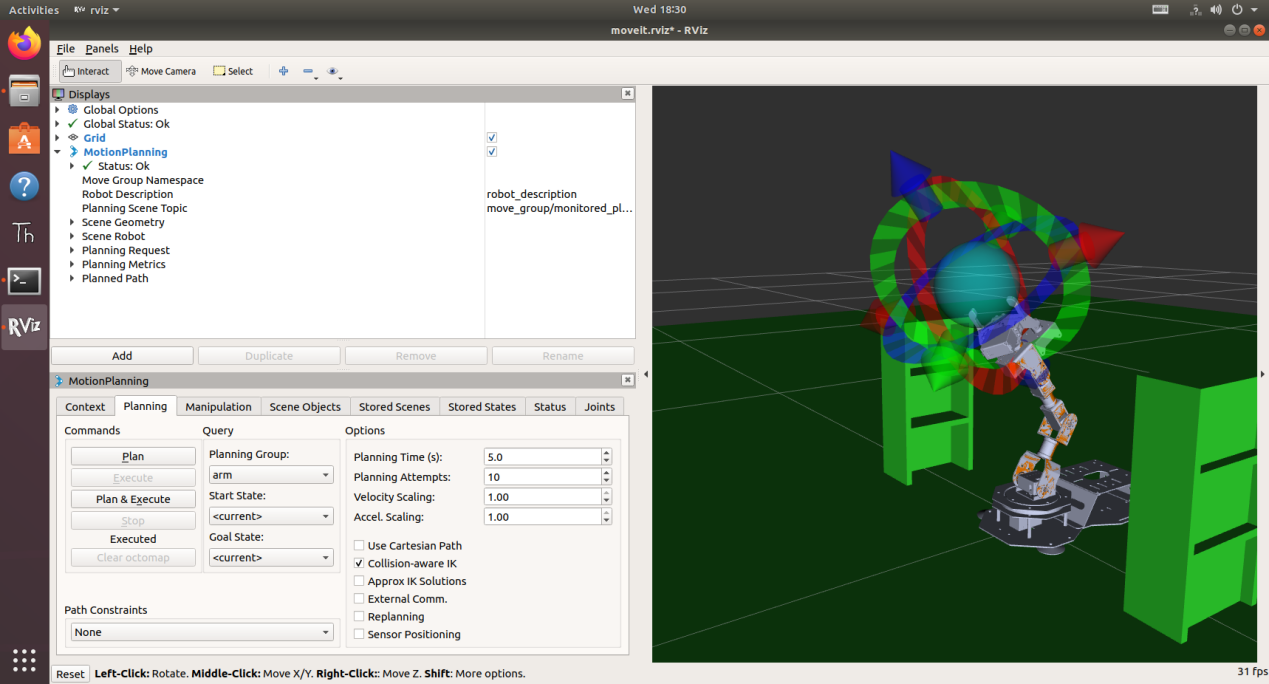
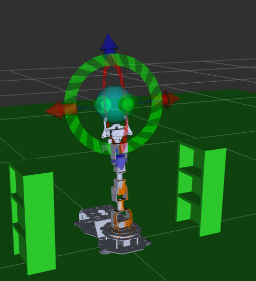
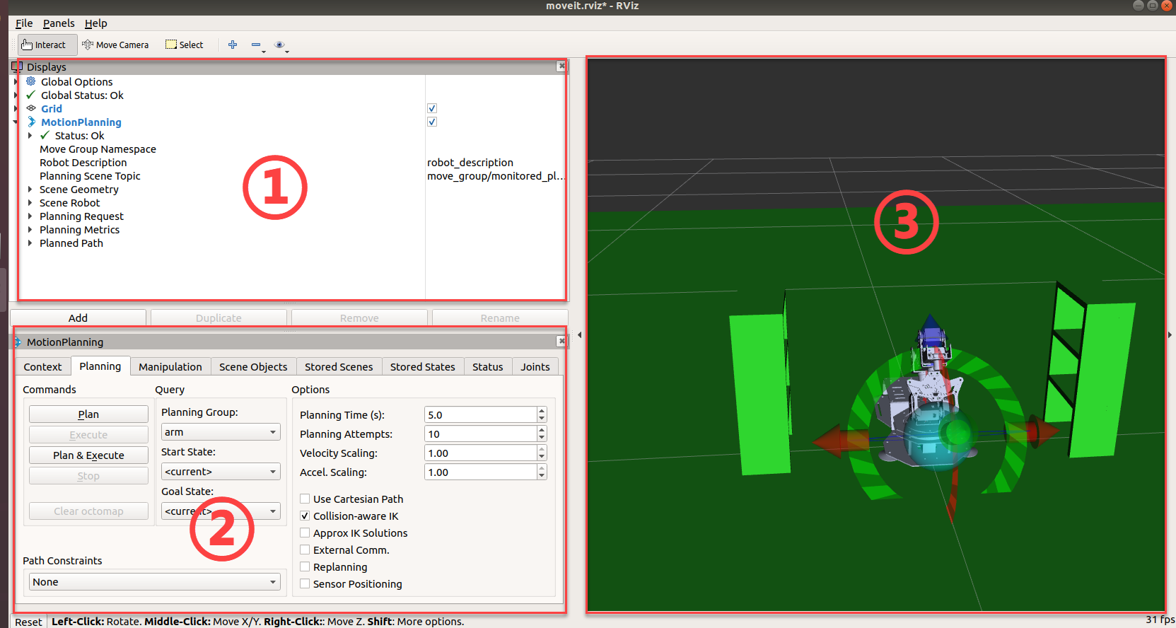
The program interface is as pictured.
Position 1 is RVIZ too bar.
Position 2 is MoveIt debug area.
Position 3 is simulation model adjusting area.

5.4.3 Control Instruction
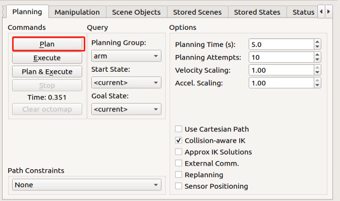
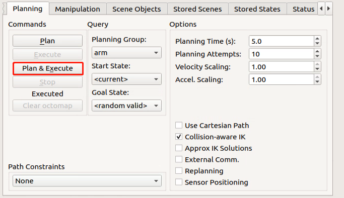
(1) Find and click “Planning” in Movelt debugging area.
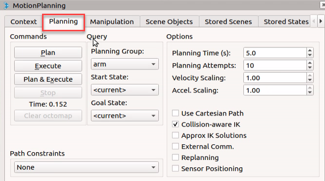
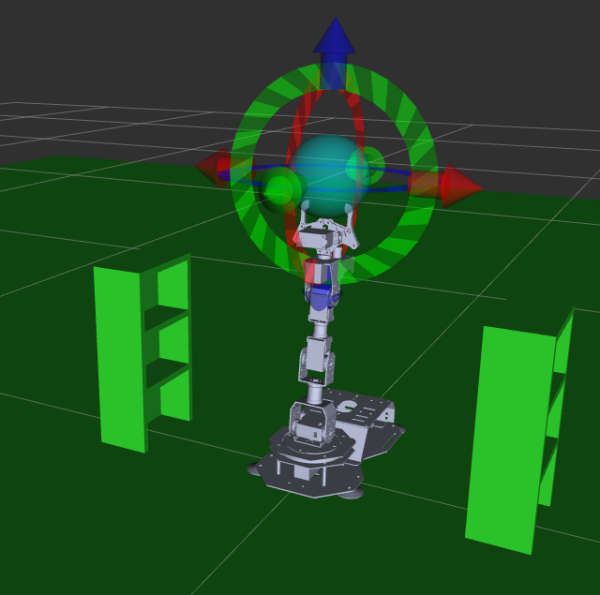
(2) With robot as the first person view, red arrow is used to control Y-axis movement, and positive Y-axis direction corresponds to robot left.
Green arrow controls X-axis movement, and positive X-axis direction
corresponds to robot front.
Blue arrow controls Z-axis movement, and positive Z-axis direction corresponds to robot top.

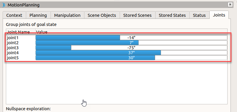
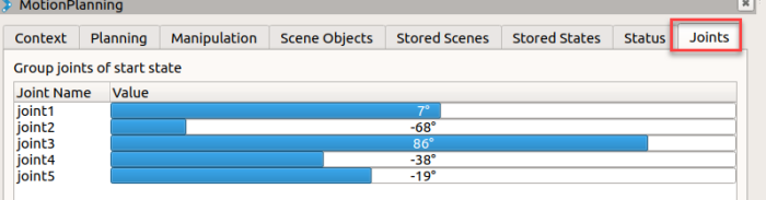
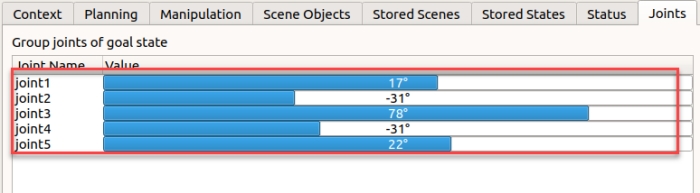
(3) Besides using arrows to adjust pose, you can directly adjust individual joint. Click “Joints”.

(4) Drag slider to adjust joint angle.
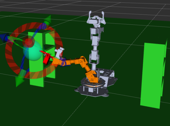
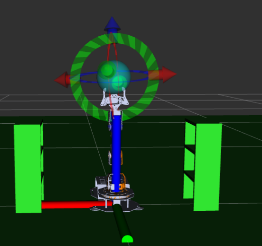
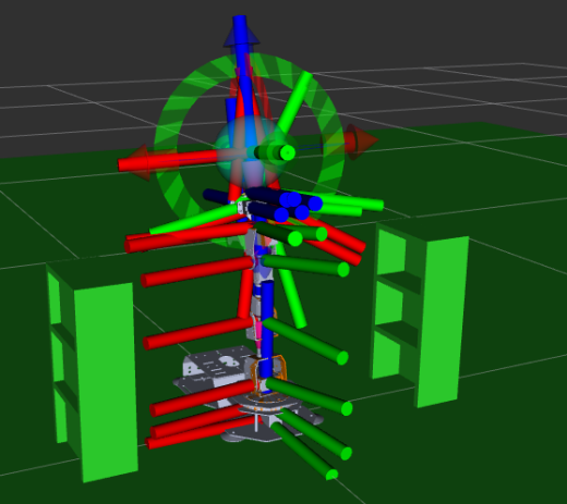
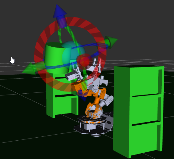
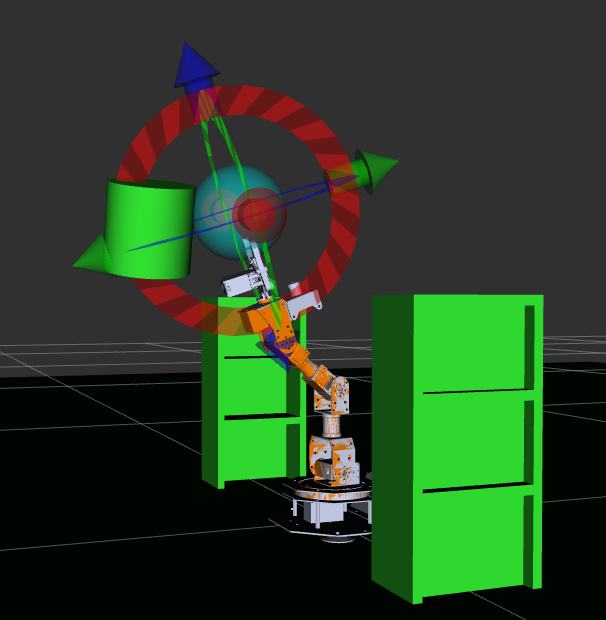
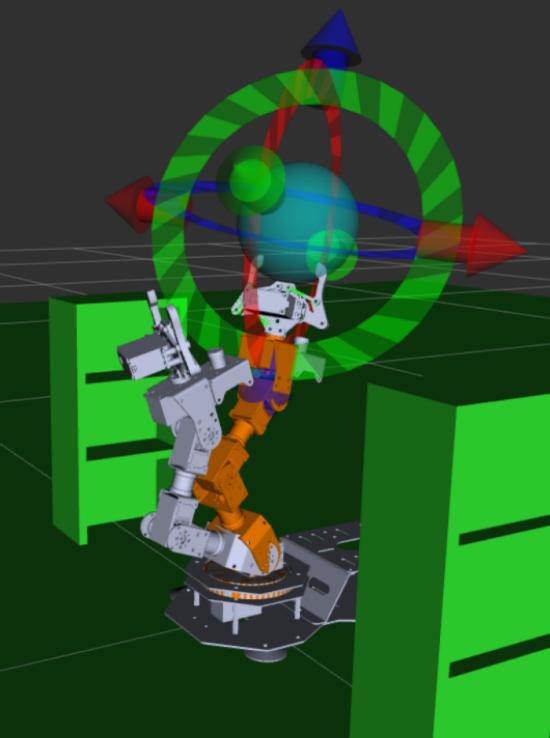
(5) After robotic arm motion path is planned successfully, new position is marked in orange as pictured. If robotic arm hit other stuffs, it will be marked in red. You need to adjust the robotic arm pose again until there is no collision, otherwise robotic arm will not perform this action.
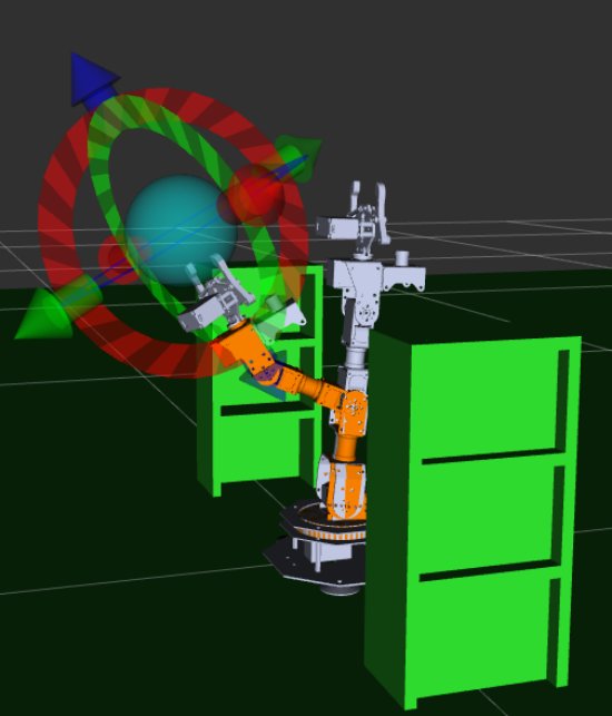
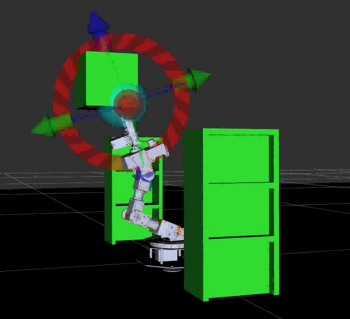
(6) For instance, if you plan the motion path as pictured, the robotic arm will hit the shelf, thus red denotes unexecutable position.
(7) Having planned the path, return back to “Planning” panel. Click “Plan” , then the animation that simulated robotic arm model moves to the specific position will be displayed.
(8) Click “Execute” to let both the simulation model and robotic arm execute the planned movement.

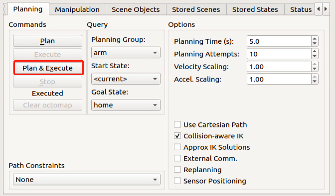
(9) Click “Plan & Execute”. Real robotic arm will take first to execute the action, then the planned motion path is demonstrated on model adjusting area.
(10) If want to exit the program, please press “Ctrl+C” . If fail to do so, please try multiple times.
5.5 Movelt Random Motion
5.5.1 Usage Precaution
Place the robot in a wide area to ensure enough motion space. Keep a certain distance from the robot to avoid hurt when robot is working. In following operations, MoveIt is used to plan the path so that control simulation model and real robot to move to specific position.
5.5.2 Enable Related Service
Note
the input command should be case sensitive, and keywords can be complemented by “Tab” key.
(1) Start ArmPi FPV, and connect it with virtual machine.
(2) Double click on  to open terminal.
(3) Open a new terminal and input command and press Enter to start MoveIt.
roslaunch armpi_fpv_moveit_config demo.launch
The program interface is as pictured.
Position 1 is RVIZ Tool Bar.
Position 2 is MoveIt debug area.
Position 3 is simulation model adjustment area.

5.5.3 Random Motion
(1) Find and click “Planning” in Movelt debug area.
(2) The arrows in simulation model adjusting area can be dragged to adjust robotic arm pose.
With robot as the first person view, red arrow is used to control Y-axis movement, and positive Y-axis direction corresponds to robot front.
Green arrow controls X-axis movement, and positive X-axis direction corresponds to robot left.
Blue arrow controls Z-axis movement, and positive Z-axis direction corresponds to robot top.
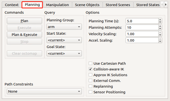
(3) Find “Query” and select joint model group in the drop-down menu of “Planning Group” , for example “arm” .

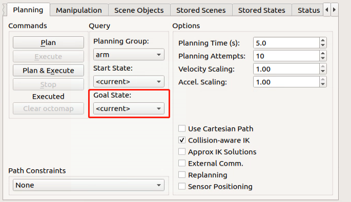
(4) Unfold drop-down manual of “Goal State” , and select target position.
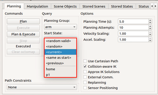
The meaning of these parameters is as follow.
random valid: valid random position. No collision will happen.
random: random position. Collision may occur.
current: current position
same as start: position that is same as the start previous: previous target position home/ p1: default position set by the program
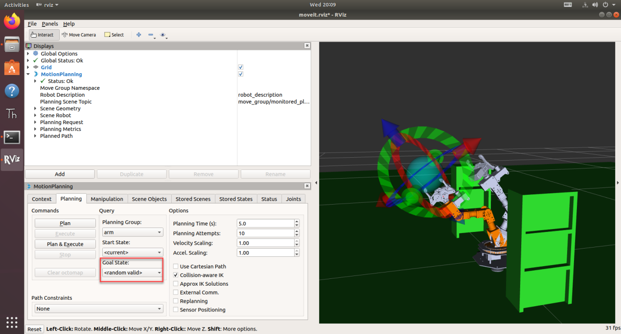
(5) To eliminate collision, select “random valid” to pick a target position randomly, and this target position will displayed on the simulation model.
(6) Click “Plan & Execute” to let both the simulation model and real robotic arm execute action at the same time. Simulation model demonstrates the planned motion path, and real robotic arm execute the action.
Note
the software will react more slowly than the robotic arm, which is normal.
(7) Press “Ctrl+C” to exit.
5.6 MoveIt Kinematics
5.6.1 Kinematic Introduction
Kinematics is a subfield of physics, developed in classical mechanics, that describes and researches the motion of objects without considering the forces that cause them to move. Forward and inverse kinematics are two computation method of robot motion.
Forward kinematics refers to process of obtaining position and velocity of end effector, given the known joint angles and angular velocities.
Inverse kinematics refers to process of obtaining robot joint angles according to the given position and pose of end effector that is calculate backward the angle that servos need to rotate based on the final position and pose of robot.
5.6.2 Forward Kinematic Analysis
DH Parameter Introduction
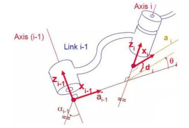
The DH parameter is a mechanical arm mathematical model and coordinate system determination system that uses four parameters to express the position and angle relationship between two pairs of joint links. As we will see below, it artificially reduces two degrees of freedom by limiting the position of the origin and the direction of the X axis, so it only needs four parameters to define a coordinate system with six degrees of freedom.
The four parameters selected by DH have very clear physical meanings, as follows:
① link length : The length of the common normal between the axes of the two joints (Rotation axis of rotation joint, translation axis of translation joint)
② link twist: The angle at which the axis of one joint rotates around theircommon normal relative to the axis of the other joint.
③ link offset: The common normal of one joint and the next joint and the distance between the common normal of one joint and the previous joint along this joint axis.
④ joint angle: The common normal of one joint and the next joint and the angle of rotation around the joint axis with the common normal of the previous joint.
The above definition is very complicated, but it will be much clearer when combined with the coordinate system.
First of all you should pay attention to the two most important “lines”: the joint axis, and the common normal between the axis joint and the adjacent joint.
In the DH parameter system, we set axis as the z axis; common normal as the x axis, and the direction of the x axis is: from this joint to the next joint.
Of course, these two rules alone are not enough to completely determine the coordinate system of each joint. Let’s talk about the steps to determine the coordinate system in detail below.
In applications such as the simulation of the robotic arm, we often adopt other methods to establish the coordinate system, but mastering the methods mentioned here is necessary for you to understand the mathematical expression of the robotic arm and understand our subsequent analysis.
The figure below shows two typical robot joints. Although such joints and links are not necessarily similar to the joints and links of any actual robot, they are very common and can easily represent any joint of the actual robot.
5.6.3 Determine the Coordinate System
To determine the coordinate system, there are generally the following steps: In order to model the robot with DH notation, the first thing is to specify a local ground reference coordinate system for each joint, so a Z axis and an X axis must be specified for each joint.
Specify the Z axis. If the joint is rotating, the Z axis is in the direction of rotation according to the right-hand rule. The rotation angle around the Z axis is a variable of the joint; if the joint is a sliding joint, the Z axis is the direction of movement along a straight line. The link length d along the Z axis is the joint variable.
Specify the X axis.When the two joints are not parallel or intersect, the Z axis is usually a diagonal line, but there is always a common vertical line with the shortest distance, which is orthogonal to any two diagonal lines. Define the X
axis of the local reference coordinate system in the direction of the common perpendicular. If an represents the common perpendicular between Zn1, the direction of Xn will be along an.
Of course there are special circumstances. When the Z axes of the two joints are parallel, there will be countless common perpendiculars. At this time, you can select the one that is collinear with the common perpendicular of the previous joint, which can simplify the model; if two joints intersect, there is no common perpendicular between them. In this case, the line perpendicular to the plane formed by the two axes can be defined as X Shaft can simplify the model.
After attaching the corresponding coordinate system to each joint, as shown in the following figure:
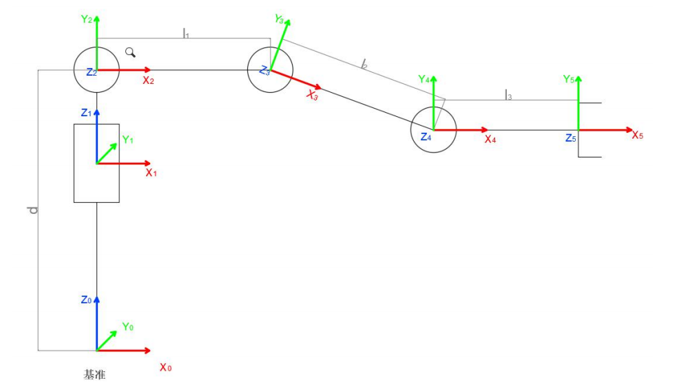
After determining the coordinate system, we can express the above four parameters in a more concise way:
link length i 1: the distance from Zi 1 to Zi along Xi 1
link twist i 1 : Zi the angle of Zi relative to Zi 1 to rotate around Xi 1
link offset i d :the distance from Xi 1 to Xi 1 along Zi
joint angle i : Xi relative to Xi 1 around Zi
Next we can write the DH parameter table of the robotic arm:
5.6.4 Inverse Kinematic Analysis
For the robot arm, the position and orientation of the gripper are given to obtain the rotation angle of each joint. The three-dimensional motion of the robotic arm is more complicated. In order to simplify the model, we remove the rotation joint of the station so that the kinematics analysis can be performed on a two-dimensional plane. Inverse kinematics analysis generally requires a large number of matrix operations, and the process is complex and computationally expensive, so it is difficult to implement. In order to better meet our needs, we use geometric methods to analyze the robotic arm.
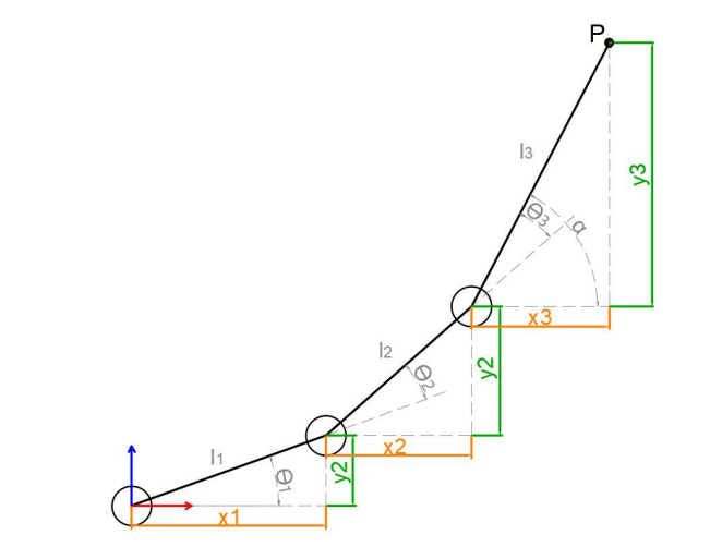
We simplify the model of the robotic arm, remove the base pan/tilt, and the actuator part to get the main body of the robotic arm. From the figure above,
you can see the coordinates (x, y) of the end point P of the robotic arm, which ultimately consists of three parts (x1+x2+x3, y1+y2+y3).
Among them θ 1, θ2,θ3 in the above figure are the angles of the servo that we need to solve, and α is the angle between the paw and the horizontal plane. From the figure, it is obvious that the top angle of the claw α=θ 1+θ2+θ3, based on which we can formulate the following formula:
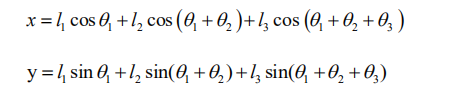
Among them, x and y are given by the user, and l1, l2, and l3 are the inherent properties of the mechanical structure of the robotic arm.
In order to facilitate the calculation, we will deal with the known part and consider the whole:
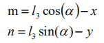
Substituting m and n into the existing equation, and then simplifying can get:
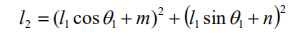
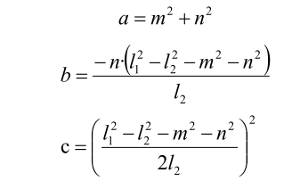
Through calculation:
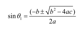
We see that the above formula is the root-finding formula of a quadratic equation in one variable:
Based on this, we can find the angle of θ 1, and similarly we can also find θ2. From this we can obtain the angles of the three steering gears, and then control the steering gears according to the angles to realize the control of the coordinate position.
5.6.5 Robotic Arm Coordinate System Introduction
(1) Base Coordinate System
With bottom servo as origin, green axis is X axis, red axis is Y axis, and blue axis is Z axis.
(2) Joint Coordinate System
Robotic arm is composed of joints and links. With pink cone as origin, green axis is X axis, red axis is Y axis and blue axis is Z axis.
(3) Tool Coordinate System
Tool is usually installed on the end of robotic arm to implement different tasks, and ArmPi FPV is equipped with gripper. Gripper coordinate system takes pink cone as origin. Green axis is X axis, red axis is Y axis and blue axis is Z axis.
5.7 MoveIt Cartesian Path
5.7.1 Introduction to Cartesian Path
(1) Cartesian Coordinate System
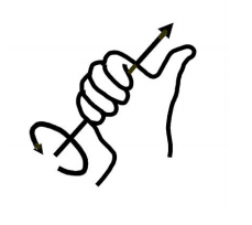
Cartesian coordinate system refers to rectangular coordinate system and oblique coordinate system. Affine coordinate system on a plane is composed of two numerical axis that intersect at origin. If unit of measure on both numerical axis are equivalent, this affine coordinate system is defined as Cartesian Coordinate System. Cartesian coordinate system whose two numerical axis are perpendicular is rectangular coordinate system, otherwise oblique coordinate system. Cartesian coordinate system is generally used to describe position, velocity and acceleration. Coordinates are usually right-handed. For right-handed coordinates the right thumb points along the z axis in the positive direction and the curl of the fingers represents a motion from the first or x axis to the second or y axis. When viewed from the top or z axis the system is counter-clockwise.
(2) Cartesian Path Planning
Cartesian path planning can be divided into two types, namely point-to-pint path planning and continuous path planning. It is a computation process where robot joint motion trajectory is computed with kinematic according to the given robot target point or path, so as to track the desired path.
(3) MoveIt Cartesian Path Analysis
Each axis of robot can be controlled through joint space which is comprised of joint vectors. Each axis moves by interpolation, and they don’t care how other axis move. The motion trajectory of robot axis end between two points is random curve. In some special cases, the motion trajectory of robotic arm end is required to be straight line or arc. Therefore, Cartesian path planing is used to restrict the shape of motion trajectory.
Note
Place the robot in a wide area to ensure enough motion space. Keep a certain distance from the robot to avoid hurt when robot is working. Bend the antenna slightly backward to avoid robotic arm from hitting the antenna.
5.7.2 Operation Steps
Note
the input command should be case sensitive, and keywords can be complemented by “Tab” key.
(1) Start ArmPi FPV, and connect it with virtual machine.
(2) Double click on  to open terminal.
(3) Open a new terminal and input command to start MoveIt.
roslaunch armpi_fpv_moveit_config demo.launch
The program interface is as pictured. Position 1 is RVIZ Tool Bar, position 2 is MoveIt debug area and position 3 is simulation model adjustment area.
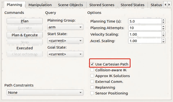
(5) Click “Planning > Use Cartesian Path” to start Cartesian path planning.
(5) Then, drag arrows in “simulation model adjust area” to plan path for robotic arm.
With robot as the first person view, red arrow is used to control Y-axis movement, and positive Y-axis direction corresponds to robot front.
Green arrow controls X-axis movement, and positive X-axis direction corresponds to robot left.
Blue arrow controls Z-axis movement, and positive Z-axis direction corresponds to robot top.


(6) Finishing planing, click “Plan & Execute” , then the simulation model will execute this action and linearly move its end effector in Cartesian space. If this action cannot be implemented resulting from Cartesian path restriction, this path planning ends in failure.
(7) Press “Ctrl+C” to exit program.
5.8 MoveIt Collision Detection
5.8.1 MoveIt Collision Detection Introduction
Collision Detection Configuration
Collision detection in MoveIt2 is configured by CollisionWorld object in planning scene. Collision detection is mainly executed by FCL software pack which is a major CC library for MoveIt2.
Collision Object
MoveIt2 welcomes different types of objects to detect collision, including: (1) Meshes (2) Basic shape: box, cylinder, cone, sphere and plane. (3) Octomap—can be directly used in collision detection
Allowed Collision Matrix(ACM)
Allowed Collision Matrix (ACM) will encode a binary value to sign whether to detect collision between objects.
If values of these two objects are set as 1, collision detection will not be executed, otherwise collision detection will continue as schedule.
Note
Place the robot in a wide area to ensure enough motion space. Keep a certain distance from the robot to avoid hurt when robot is working. Bend the antenna slightly backward to avoid robotic arm from hitting the antenna.
5.8.2 Operation Steps
Note
the input command should be case sensitive, and keywords can be complemented by “Tab” key.
(1) Start ArmPi FPV, and connect it with virtual machine.
(2) Double click on  to open terminal.
(3) Open a new terminal and input command to start MoveIt.
roslaunch armpi_fpv_moveit_config demo.launch
The program interface is as pictured. Position 1 is RVIZ Tool Bar, position 2 is MoveIt debug area and position 3 is simulation model adjustment area.

(4) Then, drag arrows in “simulation model adjust area” to plan path for robotic arm.
With robot as the first person view, red arrow is used to control Y-axis movement, and positive Y-axis direction corresponds to robot front.
Green arrow controls X-axis movement, and positive X-axis direction corresponds to robot left.
Blue arrow controls Z-axis movement, and positive Z-axis direction corresponds to robot top.
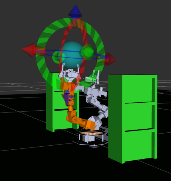
(5) New position of robot is marked in orange as pictured.

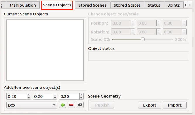
(6) After planning the path for robotic arm, click “Scene Objects” to add collision model.
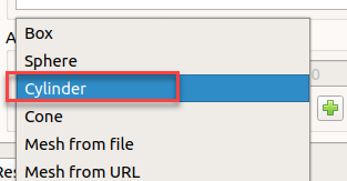
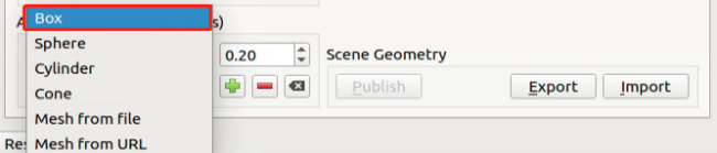
(7) Unfold “Box” drop-down menu, and select one collision model, for example “Cylinder” .

(8) Click “+” to add this collision model 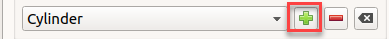
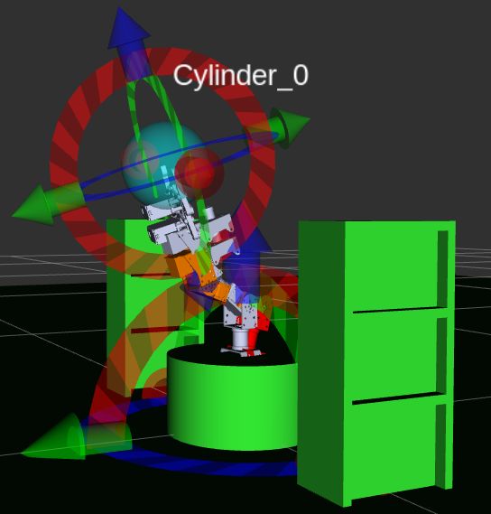
This model is generated at the bottom of the robot.
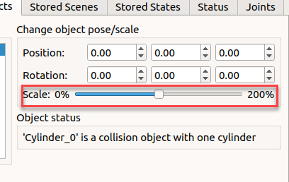
(9) Drag the slider to change model size. 50% is recommended.
(10) Drag 3D arrows of the sphere to move it between the initial position and target position.
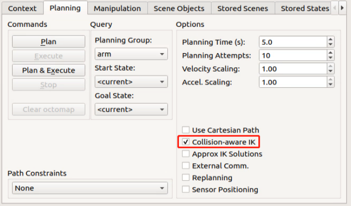
(11) Click “Planning > Collision-aware IK” to start model collision detection.

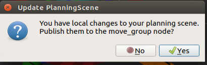
(12) Click “Plan & Execute” to start planned motion. If the following dialog box pops up, click “Yes”.
(13) After that, the robotic arm will execute the planned path while avoiding the collision model to prevent collision.
(14) Press “Ctrl+C” to exit program.
5.9 Movelt Scene Design
5.9.1 Rviz Plugin Introduction
Rviz is visualization widget provided by ROS and also a plugin of MoveIt, which allows you to visualize external information and send message to control the monitored object.
With Rviz, you can set virtual scene, set robot’s initial and target statuses, test motion planning algorithms and output 3D model.
5.9.2 Operation Steps
Note
Place the robot in a wide area to ensure enough motion space. Keep a certain distance from the robot to avoid hurt when robot is working. Bend the antenna slightly backward to avoid robotic arm from hitting the antenna.
(1) Start ArmPi FPV, and connect it with virtual machine.
(2) Double click on  to open terminal.
(3) Open a new terminal and input command to start MoveIt.
roslaunch armpi_fpv_moveit_config demo.launch
The program interface is as pictured. Position 1 is RVIZ Tool Bar, position 2 is MoveIt debug area and position 3 is simulation model adjustment area.

(4) New position of robot is marked in orange as pictured.
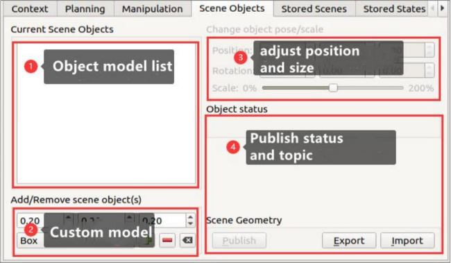
(5) Find “Scene Objects” in Movelt debugging area to add scene object model.
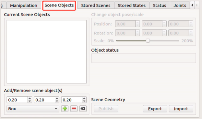
(6) This section is divided into 4 parts as pictured
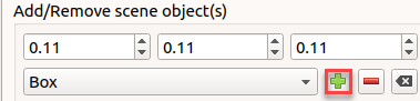
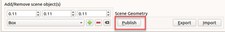
(7) Add basic model, for example Box.
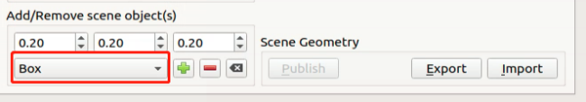
(8) Adjust the size of object model in meter.
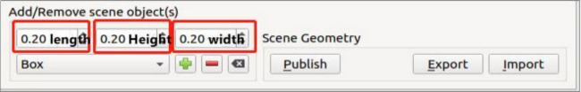
(9) After adjustment, click “+” to add the selected object model to the scene.
(10) The model list will be updated after you add the model, and the model is generated at the center of the scene i.e. center of robot
(11) Then, drag arrows in “simulation model adjust area” to plan path for robotic arm.
With robot as the first person view, red arrow is used to control Y-axis movement, and positive Y-axis direction corresponds to robot front.
Green arrow controls X-axis movement, and positive X-axis direction corresponds to robot left.
Blue arrow controls Z-axis movement, and positive Z-axis direction corresponds to robot top.
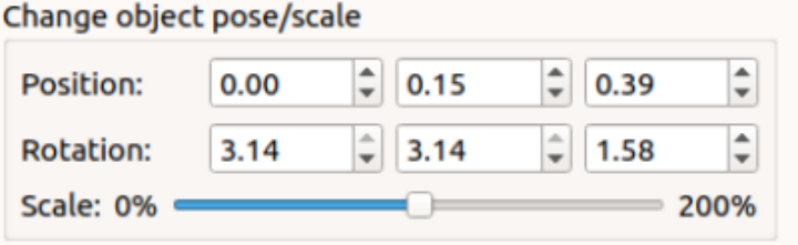
(12) Besides using arrows to adjust pose, you can adjust its pose in the area as pictured.
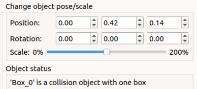
“Position” is to adjust position of object. The boxes from left to right are used to adjust X, Y and Z axis. “Rotation” is to adjust object angle. The boxes from left to right are used to adjust X, Y and Z axis. “Scale” is to adjust object size.
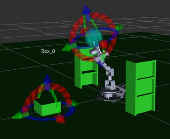
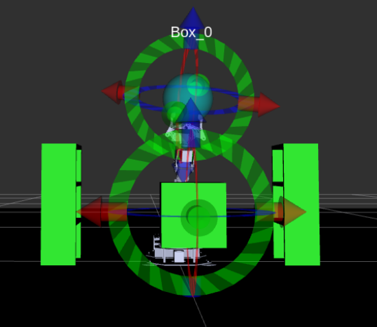
(13) For instance, adjust the position as pictured.
(14) Click “Publish” after adjustment to publish topic of this model. Movelt will subscribe to this topic automatically.
(15) To protect object model from collision, tick “Collision-aware IK” to start model collision detection.
(16) Press “Ctrl+C” to exit program.
5.10 Movelt Trajectory Planning
5.10.1 Motion Planner Introduction
Open Motion Planner Library (OMPL)
OMPL is an open robotic motion planner library based on sampling method. Most of algorithms in this library derive from RRT and RPM, for example RRTStar and RRT-Connect. By virtue of modular design, front-end GUI support and stable update, OMPL is the most mainstream motion planner software. It is default motion planner software of ROS.
A planner that is based on sampling need not take into account dimension of the planning object. That is to say no dimensional explosion will happen. A key reason why it can be used to control robotic arm is that it can effectively tackle path planning problems in high-dimensional space and complex constraints. For motion planning of N DOF robotic arm, OMPL can plan a trajectory for end effector in robotic arm joint space and create M arrays (trajectory is composed of M control points). Dimension of each array is N (joint sequence of each control point). It can ensure robotic arm will not collide with surrounding obstacles when executing this trajectory.
Industrial Motion Planner (Pilz)
Pilz industrial motion planner is a deterministic generator for circular and linear motions. In addition, it also supports integrating multiple motion segments with MoveIt2.
Stochastic Trajectory Optimization for Motion Planning
STOMP is a motion planner based on optimization and PI^2 algorithm. This planner can plan smooth trajectories, avoid obstacles and optimize constraints for the robotic arm. Arbitrary terms in the cost function can be optimized since algorithm does not require gradients.
Search-based Planning Library (SBPL)
It is a generic set of motion planners using search-based planning to discrete space
Covariant Hamiltonian Optimization for Motion Planning (CHOMP)
CHOMP is an innovative trajectory optimization based on gradient that makes ordinary motion planning simpler and more trainable.
Most high-dimensional motion planners divide the generating process of trajectory into two stages, including planning and optimization. At the stage of optimization, this algorithm employs covariant and functional gradients to design motion planning algorithm that is totally based on trajectory optimization.
Given a infeasible initial trajectory, CHOMP will make quick response to the surroundings so as to make trajectory collision-free, while optimize joint speed and acceleration.
Note
Place the robot in a wide area to ensure enough motion space. Keep a certain distance from the robot to avoid hurt when robot is working. Bend the antenna slightly backward to avoid robotic arm from hitting the antenna.
The program used in this lesson integrates OMPL and CHOMP planner, and the default planner is OMPL.
5.10.2 Operation Steps
Note
the input command should be case sensitive, and keywords can be complemented by “Tab” key.
(1) Start ArmPi FPV, and connect it with virtual machine.
(2) Double click on  to open terminal.
(3) Open a new terminal and input command to start MoveIt.
roslaunch armpi_fpv_moveit_config demo.launch
The program interface is as pictured. Position 1 is RVIZ Tool Bar, position 2 is MoveIt debug area and position 3 is simulation model adjustment area.

(4) Then, drag arrows in “simulation model adjust area” to plan path for robotic arm.
With robot as the first person view, red arrow is used to control Y-axis movement, and positive Y-axis direction corresponds to robot front.
Green arrow controls X-axis movement, and positive X-axis direction corresponds to robot left.
Blue arrow controls Z-axis movement, and positive Z-axis direction corresponds to robot top.

(5) Besides using arrows to adjust pose, you can click “Joints” to adjust individual joint.
(6) Drag sliders to adjust joint angle.
(7) After robotic arm motion path is planned successfully, new position is marked in orange as pictured. If robotic arm hit other stuffs, like depth camera, it will be marked in red. You need to adjust the robotic arm pose again until there is no collision, otherwise robotic arm will not perform this action.
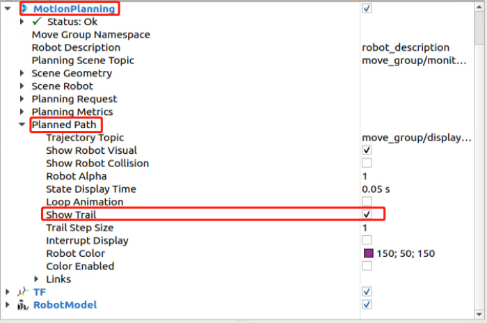
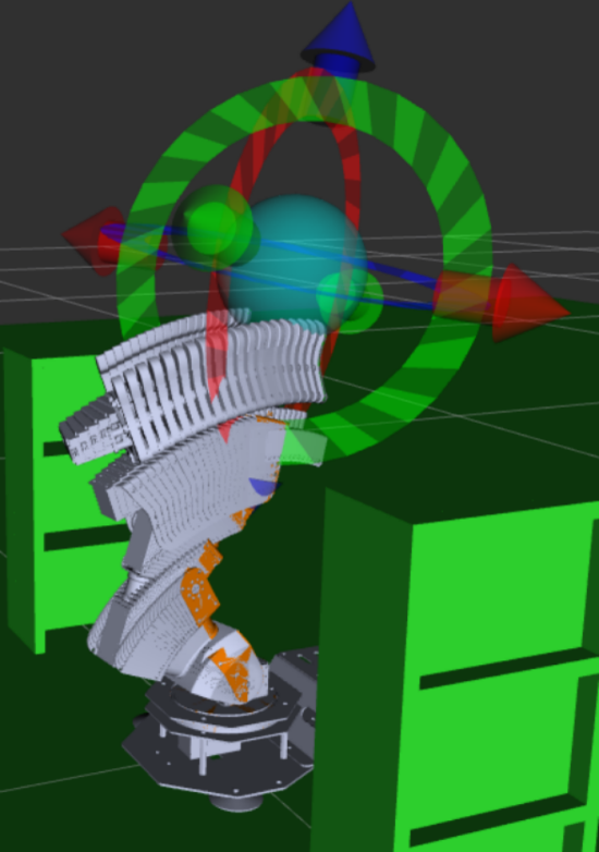
(8) Move to RVIZ tool bar, click “Motion Planning > Planned Path” , then tick “Show Trail” . The simulation model will demonstrate each frame of robotic arm motion.
(9) Return back to “Planning” section. Click “Plan” to make simulation model move to the planning position.

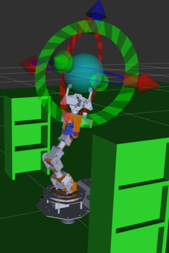
(10) After that, cancel “Show Trail”, then click “Execute” . Simulation model and robot will execute the planning action simultaneously.
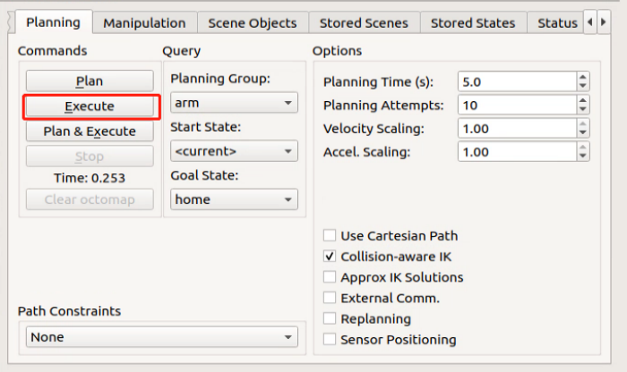
(11) Press “Ctrl+C” to exit program.