6. Python Project
6.1 MicroPython Development Environment Setup and Configuration
6.1.1 Programming Tool Installation and Overview
6.1.1.1 Firmware Flashing
Note
Before flashing the firmware, make sure to save the servo deviation values according to Read the Deviation Values in the PC Software.
Download 2. Software/5.ESP32S3 Firmware Flashing Tool/flash_download_tool_3.9.7_1. Then double-click
flash_download_tool_3.9.7.exeto open the flash tool.

Select ESP32 for ChipType and Develop for WorkMode.

Power on miniHexa and connect it to the PC.
Select 2. Software/8.miniHexa Factory Firmware/MicroPython & Scratch Firmware/minihexa_20250929_0x000.bin and set the address to
0x0000. Select the correct serial port and baud rate. Click ERASE first, then click START to begin flashing. Wait until the process is complete.

After flashing is complete, restart the robot to return it to the initial position. Then follow 6.1.2 Deviation Calibration to write the deviation values.
6.1.1.2 Python Editor Overview and Usage
This section explains how to connect the Hiwonder Python Editor and use its main features. The software allows switching the language to English.
Note
If the editor cannot be opened, rename the editor folder to an English-only name such as Hiwonder.
The editor interface is divided into five areas as shown below:

The functions of each area are listed in the table below:
| No. | Area | Function |
|---|---|---|
| 1 | Menu Bar | Includes File, Edit, View, Connect, Run, and Help. |
| 2 | Toolbar | Includes several common shortcut buttons. Their functions correspond to commands in the menu bar. |
| 3 | File List | Contains project files stored on the device and on the local PC. Folders and source code files can be viewed here. |
| 4 | Code Editor | Used to view and edit code. |
| 5 | Terminal | Displays message logs and debugging information. When no device is connected, only message logs are available. |
Operation Guide
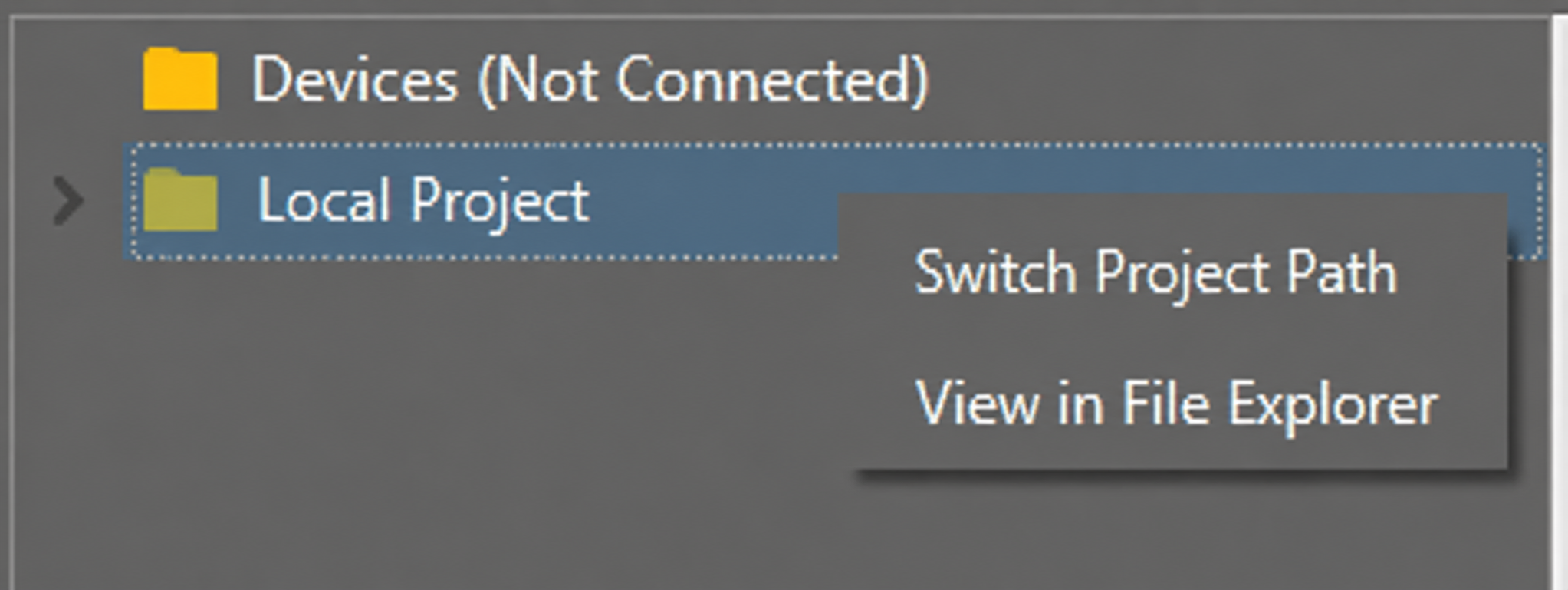
For the first import, left-click Local Project to open the file selection list. For later imports, right-click Local Project -> Switch Project Path.
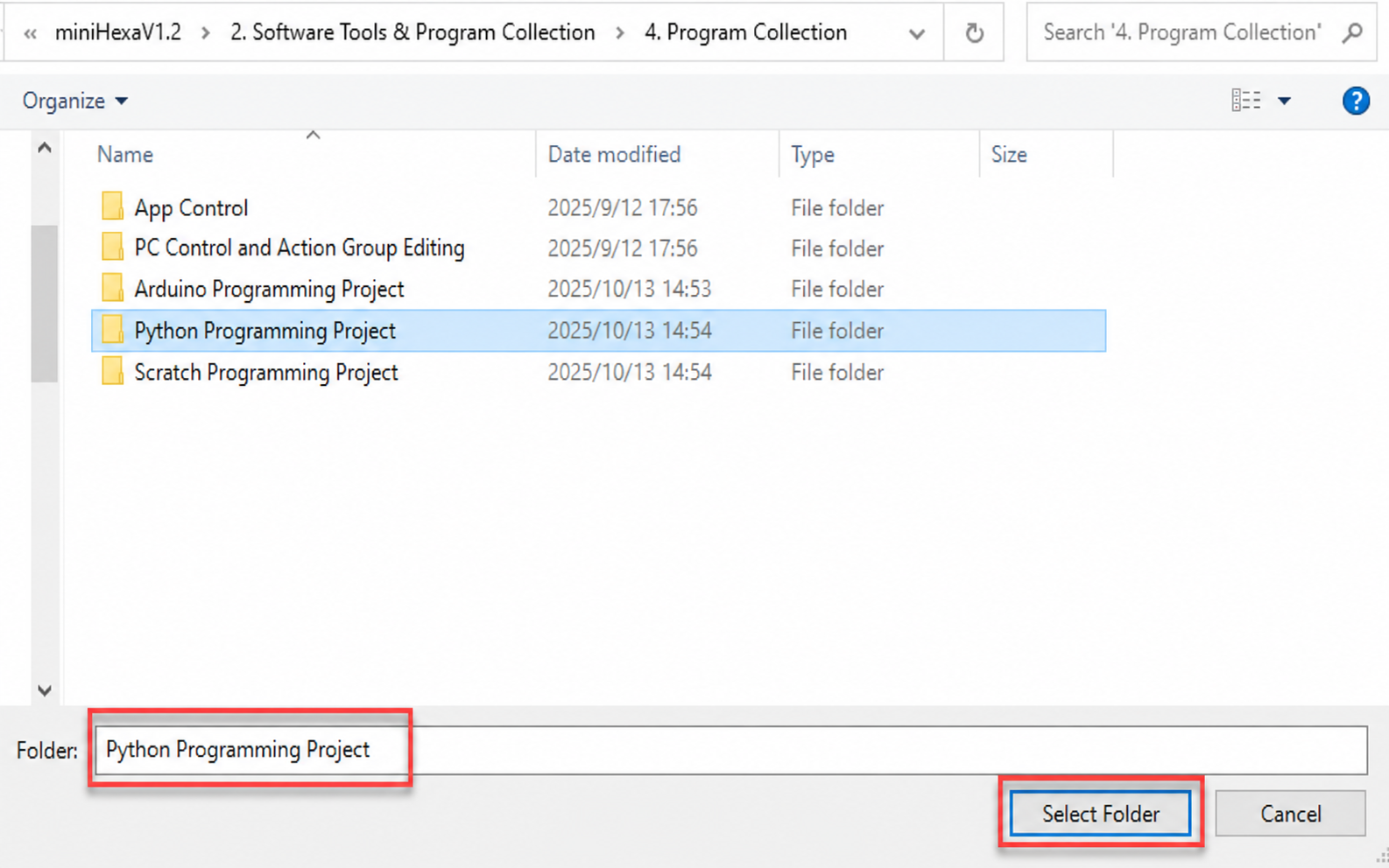
Select 2. Software/4. Program Collection/5. Python Project, then click Select Folder.
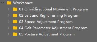
The files in the folder are automatically added to the local project and can be viewed under Local Project.
Note
Importing a local project only imports files from the PC into the editor. It does not download them to the ESP32 controller board.
View Files and Programs
Double-click a program file in the file list to view the code. 02 Omnidirectional Movement Program/main.py is used here as an example:
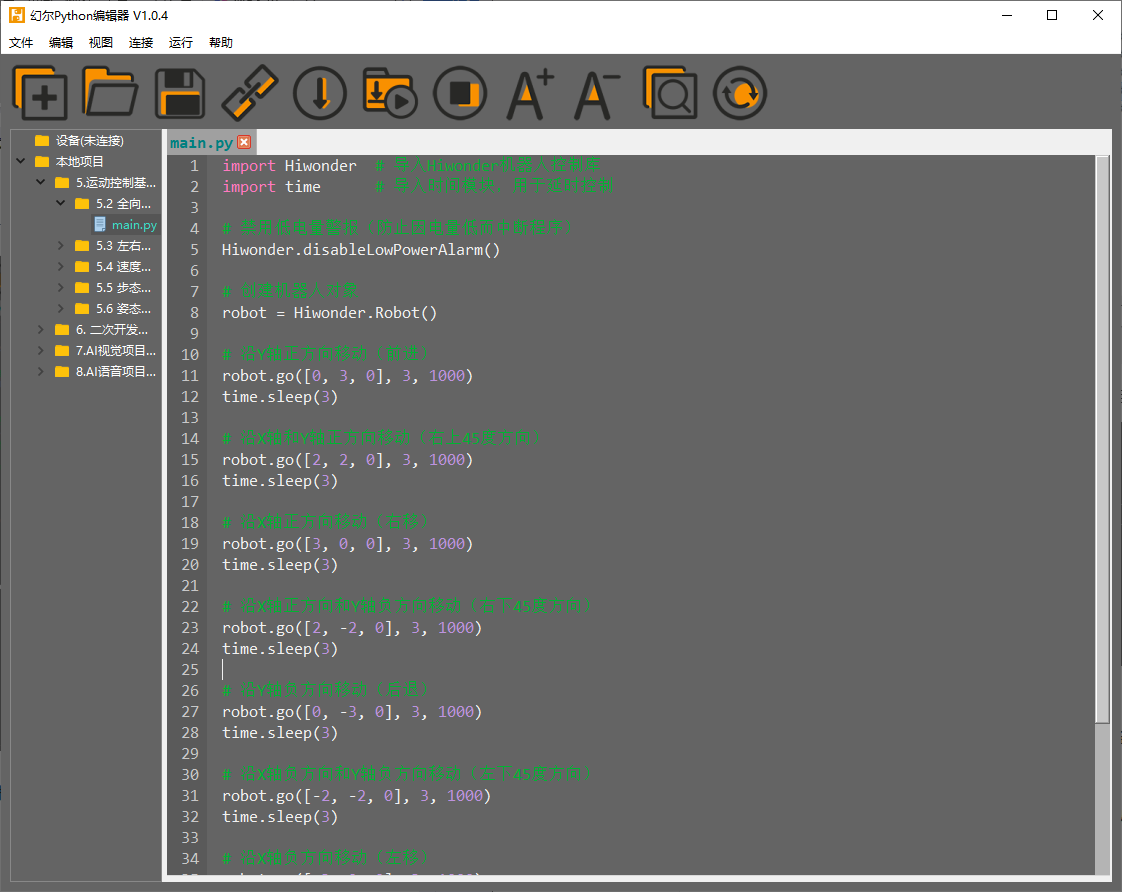
After a program file is downloaded to the ESP32 controller board, double-click the file under Device to view it in the same way.
Code Writing and Saving
The code editor on the right side supports code creation, viewing, editing, modification, and saving. Read the following notes before writing code:
Files cannot be created directly under the Device tab. Changes to files under Device can be saved only through the download operation. For backup, copy the files to the local project first.
Do not modify action group files with the
.robextension in the editor. Unknown format errors may occur. Edit action group files in the PC software when needed.Among the provided low-level program files,
main.pyis the main program of the device. All robot functions are launched through this file. Reset and power-on operations also depend on this file. Ifmain.pystops responding, subsequent operations cannot continue. For safety, rename the program first if additional features need to be added. Ifmain.pyis changed to another name and the program becomes stuck during debugging, even when Ctrl+C and Ctrl+D both fail, reset the controller board, delete the program, and download the required program again.
Program Download and Execution
Program download is an interaction between the editor and the device. 02 Omnidirectional Movement Program/main.py is used here as an example:
Under the Local Project tab, select
02 Omnidirectional Movement Program/main.py. Click the toolbar icon to connect to the ESP32 controller board. Then click the toolbar icon
  or right-click the file and select Download and Run.

The terminal displays the download progress and completion status. Since Download and Run is used in the previous step, the running result can also be viewed there.

After the download is complete, the program appears in the file list under Device.

Note
If the downloaded file is not named
main.py, delete the originalmain.pyand rename the downloaded file tomain.py. Another option is to rename the file tomain.pybefore downloading.“Download and Run” first resets the device, which means a restart, and then downloads and runs the program. This helps improve program stability.
If the program does not need to run immediately, click the button
 or right-click the target file and select “Download”. Before running the program later, click the icon
  to reset the device first, then run the program.
Terminal Debugging
The terminal combines the message window and the debugging console. When no device is connected, the terminal can display messages only and cannot be used for editing or debugging. The message viewing function has already been shown in the previous steps. The following section focuses on debugging features.
The terminal supports code input. Enter
print(123)in the terminal and press Enter. The result is shown below:

The terminal also supports automatic indentation. When a Python statement ends with a colon, such as
if,for, orwhile, pressing Enter continues on the next line with the appropriate indentation. Press Backspace to remove one indentation level.

To copy and paste code, select the target code and right-click in the terminal.

Note
Press “Ctrl+E” to enter edit mode before pasting code. Otherwise, indentation errors may occur during debugging.
The image below shows the correct result after copy and paste. The indentation is correct.

The image below shows incorrect indentation:

To exit edit mode, press Ctrl+C. If an infinite loop is running, press Ctrl+C to interrupt it as well.
Note
“Ctrl+C” only interrupts a running program in the terminal. It does not copy text. “Ctrl+V” does not paste text in the terminal.
Use Tab to complete code when entering commands in the terminal. For example, enter
osand press Tab. The result is shown below:

If two or more completions are available, the terminal lists all available options. If only one completion is available, the terminal completes it automatically. If no completion is available, no action is taken.
Use the Up Arrow and Down Arrow keys in the terminal to view previously entered commands and reduce repeated input.
For more commands and command descriptions, visit http://docs.micropython.org/en/latest/library/uos.html
6.1.2 Deviation Calibration
6.1.2.1 Read the Deviation Values in the PC Software
Downloading an Arduino program erases the MicroPython firmware on the ESP32. The original servo deviation values are cleared at the same time. Before programming a MicroPython project, open the PC software and save the servo deviation values.
Open 2. Software/3. PC Software Package/MiniHexa.exe. Connect miniHexa to the PC with a USB data cable. Then follow the steps shown below. Select the corresponding port.
COM4is used here as an example. Click Connect, then click Action Edit.

Click Read offset to read the servo deviation values.

Note
After the servo deviation values are read, take a screenshot to keep a backup and prevent data loss.
6.1.2.2 Write the Deviation Values
Open the Hiwonder Python Editor.

Open 02 Program Files/Deviation Writing Program/main.py, then drag it into the Hiwonder Python Editor. The drag operation takes effect only when the file is dropped inside the red box.

Locate the code section that sets the deviation values:
# Set servo deviation values
robot.set_deviation(1 , 0)
robot.set_deviation(2 , 0)
robot.set_deviation(3 , 0)
robot.set_deviation(4 , 0)
robot.set_deviation(5 , 0)
robot.set_deviation(6 , 0)
robot.set_deviation(7 , 0)
robot.set_deviation(8 , 0)
robot.set_deviation(9 , 0)
robot.set_deviation(10 , 0)
robot.set_deviation(11 , 0)
robot.set_deviation(12 , 0)
robot.set_deviation(13 , 0)
robot.set_deviation(14 , 0)
robot.set_deviation(15 , 0)
robot.set_deviation(16 , 0)
robot.set_deviation(17 , 0)
robot.set_deviation(18 , 0)
Write the deviation data read in Read the Deviation Values in the PC Software into the code.
robot.set_deviation(1 , 24)
robot.set_deviation(2 , 28)
robot.set_deviation(3 , 9)
robot.set_deviation(4 , -20)
robot.set_deviation(5 , -13)
robot.set_deviation(6 , -13)
robot.set_deviation(7 , 0)
robot.set_deviation(8 , -7)
robot.set_deviation(9 , 14)
robot.set_deviation(10 , 21)
robot.set_deviation(11 , -11)
robot.set_deviation(12 , 16)
robot.set_deviation(13 , 21)
robot.set_deviation(14 , 31)
robot.set_deviation(15 , -5)
robot.set_deviation(16 , 0)
robot.set_deviation(17 , -33)
robot.set_deviation(18 , -9)
After setting the deviation values, connect miniHexa to the PC with a Type-C data cable. Click
. After the connection is successful, the icon turns green  . Then click to download the program to miniHexa.

Note
The deviation setting program needs to be downloaded and run on miniHexa only once. After that, the settings are stored in the miniHexa Arduino programming environment. No additional setup is required.
6.1.2.3 Read the Written Deviation Values
After the deviation values are written, click . The serial port continuously prints the stored servo deviation values.

6.2 Basic Motion Control
6.2.1 Kinematics and Gait Overview
6.2.1.1 Coordinate System Introduction
To control miniHexa, specify the contact point coordinates of the six legs. Inverse kinematics is then used to calculate the rotation angles of all servos, which controls the movement of miniHexa.
First establish the coordinate system of miniHexa. Use the center of the body as the origin
0, 0, 0. From the robot’s own perspective, the front is the positive Y-axis, the right side is the positive X-axis, and the upward direction is the positive Z-axis, as shown below:

When setting coordinates, only the X-axis, Y-axis, and Z-axis values of the six leg contact points need to be specified.
6.2.1.2 Gait Overview
Gait is a periodic summary of the walking characteristics of animals. In simple terms, it describes how an animal walks. Common gait patterns of hexapods include tripod gait and wave gait. Under all conditions, at least three legs must remain in contact with the ground to keep the system stable.
The table below lists several common terms used in gait descriptions:
| Term | Description |
|---|---|
| Phase | The position in periodic motion. The most direct interpretation is angle. |
| Phase Difference | The lead or lag difference in motion between different legs. |
| Swing Phase | The leg is lifted and off the ground. |
| Stance Phase | The leg is in contact with the ground. |
| Cycle | During locomotion, the complete process from one touchdown of the foot to the next touchdown of the same foot is one cycle. |
| Gait Frequency | The number of gait cycles completed per unit time. |
| Step Length | The distance traveled by the foot endpoint from lift-off to touchdown within one cycle. |
| Stride Length | The distance traveled by the body within one cycle. |
| Duty Cycle | The ratio between the time a single leg stays in the stance phase and the gait cycle. |
6.2.1.3 Tripod Gait Introduction
Tripod gait is a typical walking gait for hexapod robots. In six-legged insects, all six legs do not move forward at the same time. Instead, the three pairs of legs are divided into two groups and advance alternately in a triangular support structure. In simple terms, three legs move up and down alternately with the other three.
This triangular support structure keeps the body in a statically stable state.
Most hexapod robots currently use an insect-inspired structure. The six legs are distributed on both sides of the body. The front and rear legs on the left side together with the middle leg on the right side form one group. The front and rear legs on the right side together with the middle leg on the left side form the other group. These two groups form two triangular supports. Support and swing are achieved through the forward and backward swing of the thighs. This is the typical tripod gait walking method.
When the hexapod robot uses tripod gait, the two leg groups operate alternately. For clarity, the legs are numbered from the robot’s own perspective as shown below:

The diagram below is used to analyze tripod gait:

As shown on the right side of the figure, legs 2, 4, and 6 lift and swing forward. Legs 1, 3, and 5 support the body and keep the center of gravity at the intersection of the diagonals. At this time, legs 2, 4, and 6 are in the swing phase. Legs 1, 3, and 5 are in the stance phase.
Then all six legs touch the ground at the same time. Legs 1, 3, and 5 stay in place. Legs 2, 4, and 6 are farther forward. All legs are in the stance phase.
As shown on the left side of the figure, legs 1, 3, and 5 lift and swing forward. Legs 2, 4, and 6 support the body and keep the center of gravity at the intersection of the diagonals. At this time, legs 1, 3, and 5 are in the swing phase. Legs 2, 4, and 6 are in the stance phase.
Then all six legs touch the ground at the same time. Legs 2, 4, and 6 stay in place. Legs 1, 3, and 5 are farther forward. All legs are in the stance phase.
After these four actions are completed, the robot completes one full gait cycle.
6.2.1.4 Robot Motion Process Analysis
This section uses one leg as an example to explain the motion process from the standing standby stage to the final standing return stage after movement is completed. For ease of description, assume the robot is standing still and receives a command to move straight forward.
Initial Stage
Before the robot receives the motion command, observe the middle leg in the figure below. It is touching the ground.

After the robot receives the motion command, overall movement begins. When the observed leg is ready to move, it lifts upward to the position directly above, which is the initial position, as shown below.

Motion Stage
During the motion stage, the leg always starts moving from the initial position.
Based on the motion parameters, the robot controls the leg to swing forward or backward. In the assumed scenario, the robot moves forward, so the leg first swings forward from top to bottom until the toe touches the ground, as shown below.

After the toe touches the ground, the leg continues to swing backward. The resulting force drives the robot forward, as shown below.

Finally, the leg swings upward from bottom to top and returns to the initial position. This completes one full motion cycle of the leg. In the
movefunction, which is used to control body movement, the movement step countstep_numcan be specified. The movement step count refers to how many cycles one leg completes, starting from the initial position, landing on the ground, and swinging back to the initial position.

Finishing Stage
After the leg completes the last swing, it enters the finishing stage. The motion still starts from the initial position.
As shown below, the leg drops to the ground and completes the final finishing movement.
6.2.1.5 Robot Kinematics Analysis
Because the overall motion of the robot involves the coupling of the gait algorithm and the inverse kinematics algorithm, analyzing the full system directly is relatively complex. Therefore, one leg is used here as an example so that the gait algorithm can be separated from the discussion and the kinematics can be analyzed directly.
Single-Leg Structural Modeling
The figure below shows the coordinate-system model of a single leg:

Note
In the actual design, a metal plate is mounted at joint
O3at the end of the leg. Its width extends in the same direction as link r2. Therefore, in the following calculations, that width is treated as the foot-end offsetoffsetand is included as part of link r2.In the D-H parameter table and in the forward and inverse kinematics derivations below, r2 already includes the foot-end offset
offset.
D-H Parameter Table
| i | d | theta | r | alpha |
|---|---|---|---|---|
| 1 | 0 | 0 | 2.85 | 90 |
| 2 | 0 | 0 | 5.2 | 0 |
| 3 | 0 | 0 | 7.2 | 0 |
Description of the four D-H parameters:
d is the offset of coordinate system a(i+1) relative to coordinate system a(i) along the Z(i) axis
theta is the angle between the X-axes of coordinate systems a(i) and a(i+1)
r is the mathematical length of the link
alpha is the angle from Z(i-1) to Z(i+1) after rotation around X(i)
Single-Leg Forward Kinematics Overview
Forward kinematics is a fundamental basis for trajectory planning in joint space and for robot control. For this robot, forward kinematics means calculating the foot-end coordinates from the rotation angles of the three servos on one leg.
The forward kinematics process is as follows: given the rotation angles of the three servos on one leg, determine the leg position and then calculate the corresponding foot-end coordinates.
Single-Leg Forward Kinematics Derivation
Known parameters: joint rotation angles Q1, Q2, and Q3
Unknown parameters: the D-H parameter table and the foot-end coordinates px, py, and pz
The transformation matrix expressions of each joint coordinate system are obtained as follows:
By multiplying the matrices sequentially, the overall transformation matrix T14 from the base coordinate system to the foot endpoint coordinate system can be obtained:
Here px, py, and pz are the end-point coordinates, namely the foot-end coordinates. Their expressions are as follows:
After further simplification:
This yields the forward kinematics expressions that map servo rotation angles to foot-end coordinates.
Single-Leg Inverse Kinematics Overview
Inverse kinematics is a fundamental basis for trajectory planning based on the end effector and for robot control. For this robot, inverse kinematics means calculating the rotation angles of the three servos on one leg from the foot-end coordinates.
The inverse kinematics process is as follows: given the foot-end coordinates of one leg, determine the leg position and then solve for the corresponding servo rotation angles.
After the servo rotation angles are obtained, the corresponding values can be calculated to drive the servos directly and achieve robot motion control.
Single-Leg Inverse Kinematics Derivation
Known parameters: the D-H parameter table and the foot-end coordinates px, py, and pz
Unknown parameters: joint rotation angles Q1, Q2, and Q3
First, define a matrix that contains the known foot-end coordinates. It will later be multiplied by other matrices containing Q1, Q2, and Q3 so that several expressions can be derived for further solving. From the forward kinematics derivation above, T14 meets this requirement. Only the first three elements of the fourth column need to be considered here because they are known values:
Based on the expression of the transformation matrix:
Derive the expressions on both sides:
By equating the first three elements of the fourth column of these two matrices, three expressions are obtained:
(1-1)
(1-2)
(1-3)
Further derivation of equation
(1-3)gives the expression for Q1 in terms of px, py, and pz:
By observing equations
(1-1)and(1-2), it can be seen that the two expressions contain trigonometric functions of Q2 and Q2+Q3. The next step is to simplify them using the identity sin2x + cos2x = 1. First, isolate the parts that are not trigonometric functions of Q2 and Q2+Q3, and consolidate them into m1 and m2. Since Q1 has already been obtained above, both m1 and m2 are known values.
After simplification, equations
(1-1)and(1-2)can be rewritten as:
(1-4)
(1-5)
Square both sides of equations
(1-4)and(1-5), then add the left-hand sides and the right-hand sides respectively to obtain:
(1-6)
Further consolidate parts of the expression above. From the following definitions, n1, n2, and n3 are all known values:
After further simplification of equation
(1-6):
Further derivation yields the expression for Q2 in terms of px, py, and pz:
Substitute the expression for Q2 back into equation
(1-4)or(1-5)to obtain the expression for Q3:
After consolidation, the inverse kinematics expressions for the joint rotation angles Q1, Q2, and Q3 are listed again below:
6.2.2 Omnidirectional Movement
6.2.2.1 Feature Overview
This section controls miniHexa to move in different directions.
6.2.2.2 Project Process

6.2.2.3 Program Download
Connect miniHexa to the PC with a Type-C data cable.

Open 02 Program Files/01 Omnidirectional Movement Program/main.py in the same path as this document.

After the file is opened, select the development board model shown below:

Click Tools in the menu bar and select the corresponding ESP32 development board configuration as shown below.

Note
Make sure to modify the development board configuration before program download.
Click Compile first, then click Upload. When the output panel at the bottom displays the success message, the program has been downloaded successfully.

6.2.2.4 Project Outcome
After power-on, the hexapod robot cycles through movement in ten directions: forward, forward-right, right, backward-right, backward, backward-left, left, forward-left, turn left in place, and turn right in place.
6.2.2.5 Program Analysis
Import the
hiwonder_robot.hlibrary file. This library contains the low-level control interfaces of the robot.
#include "hiwonder_robot.h"
Initialize the
miniHexaobject and define the motion mode variablecount. Then create the robot motion arraysvel,pos, andatt, which represent velocity, position, and Euler angles.
    // Initialize miniHexa object
    Robot minihexa;

    // Define variable `count` to record the motion mode
    uint8_t count = 0;
    // Initialize motion state
    Velocity_t vel = {0.0f,0.0f,0.0f};
    Vector_t pos = {0.0f,0.0f,0.0f};
    Euler_t att = {0.0f,0.0f,0.0f};
In the
setup()function, set the initial serial communication baud rate to115200, then initialize the robot.
   void setup() {
     Serial.begin(115200);
     minihexa.begin();
   }
In the
loop()main function, the ten different movement directions are executed cyclically according to the loop of variablecount. By modifying the three parameters invel, the direction of body movement can be changed. The first parameter ofvelcontrols the left and right movement speed of the body along the X-axis. The second parameter controls the forward and backward movement speed of the body along the Y-axis. The third parameter controls the in-place rotation speed of the body around the Z-axis. Aftervelis passed into themovefunction, the robot starts moving according to the specified parameters. After5.5 s, the next group of motion parameters is passed into themovefunction, and the robot switches to the next motion state.
    void loop() {
      switch(count) {
        case 0:// Forward
          count++;
          vel = {0.0f, 3.0f, 0.0f};
          break;

        case 1:// Forward-right
          count++;
          vel = {2.0f, 2.0f, 0.0f};
          break;

        case 2:// Move right
          count++;
          vel = {3.0f, 0.0f, 0.0f};
          break;

        case 3:// Backward-right
          count++;
          vel = {2.0f, -2.0f, 0.0f};
          break;

        case 4:// Backward
          count++;
          vel = {0.0f, -3.0f, 0.0f};
          break;

        case 5:// Backward-left
          count++;
          vel = {-2.0f, -2.0f, 0.0f};
          break;

        case 6:// Move left
          count++;
          vel = {-3.0f, 0.0f, 0.0};
          break;

        case 7:// Forward-left
          count++;
          vel = {-2.0f, 2.0f, 0.0f};
          break;

        case 8:// Turn left in place
          count++;
          vel = {0.0f, 0.0f, 2.0f};
          break;

        case 9:// Turn right in place
          count = 0;
          vel = {0.0f, 0.0f, -2.0f};
          break;
      }
      delay(5500);
      minihexa.move(&vel, &pos, &att, 1800, 3);
    }
case 0is used here as an example. The movement direction of the body is mainly changed by modifying the parameters ofvel. When the Y-axis speed is set to3, the body moves forward.
    case 0:// Forward
      count++;
      vel = {0.0f, 3.0f, 0.0f};  // Set the Y-axis speed to 3 so the body moves forward
      break;
case 1is used here as an example. Set the X-axis speed to2so the body translates to the right. Then add a Y-axis speed of2so the body moves forward. Under the combined effect of these two directions, the body moves toward the forward-right direction.
    case 1:// Forward-right
      count++;
      vel = {2.0f, 2.0f, 0.0f};  // X-axis speed 2 to the right and Y-axis speed 2 forward
      break;
case 8is used here as an example. Set the Z-axis speed to2.0f, and the body rotates to the left in place.
    case 8:// Turn left in place
      count++;
      vel = {0.0f, 0.0f, 2.0f};  // Z-axis speed 2 so the body turns left in place
      break;
6.2.3 Turn Left and Right
6.2.3.1 Feature Overview
This section controls miniHexa to perform left and right turning motion.
6.2.3.2 Project Process

6.2.3.3 Program Download
Connect miniHexa to the PC with a Type-C data cable.

Open 02 Program Files/02 Left and Right Turning Program/main.py in the same path as this document.

After the file is opened, select the development board model shown below:

Click Tools in the menu bar and select the corresponding ESP32 development board configuration as shown below.

Note
Make sure to modify the development board configuration before program download.
Click Compile first, then click Upload. When the output panel at the bottom displays the success message, the program has been downloaded successfully.

6.2.3.4 Project Outcome
After power-on, the hexapod robot repeatedly performs left and right arc turns.
6.2.3.5 Program Analysis
Import the
hiwonder_robot.hlibrary file. This library contains the low-level control interfaces of the robot.
#include "hiwonder_robot.h"
Initialize the
miniHexaobject and create the robot motion arraysvel,pos, andatt, which represent velocity, position, and Euler angles.
    // Initialize miniHexa object
    Robot minihexa;

    // Initialize motion state
    Velocity_t vel = {0.0f,0.0f,0.0f};
    Vector_t pos = {0.0f,0.0f,0.0f};
    Euler_t att = {0.0f,0.0f,0.0f};
In the
setup()function, set the initial serial communication baud rate to115200, then initialize the robot.
    void setup() {
      Serial.begin(115200);
      minihexa.begin();
    }
In the
loop()main function, the robot repeatedly performs left and right turns by changing thevelarray. First execute a left arc turn. Set the Y-axis speed invelto5so the robot translates forward. Set the Z-axis speed to0.2so the robot rotates to the left. The combined effect of these two motions makes the robot turn left.
    void loop() {
        vel = {0.0f, 5.0f, 0.2f};// Left arc forward
        minihexa.move(&vel, &pos, &att);// Execute movement
        delay(5000);
    }
Set the Y-axis speed to
5and the Z-axis speed to-0.2to make the robot turn right.
        vel = {0.0f, 5.0f, -0.2f};// Right arc forward
        minihexa.move(&vel, &pos, &att);// Execute movement
        delay(5000);
    }
6.2.3.6 Feature Extension
This section uses changing the turning angle of miniHexa as an example to show how to modify the turning angle. Refer to the steps below:
Locate the turning code in the main function.
    void loop() {
        vel = {0.0f, 5.0f, 0.2f};// Left arc forward
        minihexa.move(&vel, &pos, &att);// Execute movement
        delay(5000);

        vel = {0.0f, 5.0f, -0.2f};// Right arc forward
        minihexa.move(&vel, &pos, &att);// Execute movement
        delay(5000);
    }
Modify the third value
omegainvel. Here it is changed to0.3fto increase the turning angle.
Note
The third omega value in vel should not be set too high. Otherwise, the effect of left rotation will greatly exceed the effect of forward translation, and the robot will behave more like it is rotating in place.
void loop() {
    vel = {0.0f, 5.0f, 0.3f};// Left arc forward with a larger turning angle
    minihexa.move(&vel, &pos, &att);// Execute movement
    delay(5000);

    vel = {0.0f, 5.0f, -0.3f};// Right arc forward with a larger turning angle
    minihexa.move(&vel, &pos, &att);// Execute movement
    delay(5000);
}
After the modification is completed, refer to 6.2.3.3 Program Download to run the program.
6.2.4 Speed Adjustment
6.2.4.1 Feature Overview
This section controls miniHexa to move at different speeds.
6.2.4.2 Project Process

6.2.4.3 Program Download
Connect miniHexa to the PC with a Type-C data cable.

Open 02 Program Files/03 Speed Adjustment Program/main.py in the same path as this document.

After the file is opened, select the development board model shown below:

Click Tools in the menu bar and select the corresponding ESP32 development board configuration as shown below.

Note
Make sure to modify the development board configuration before program download.
Click Compile first, then click Upload. When the output panel at the bottom displays the success message, the program has been downloaded successfully.

6.2.4.4 Project Outcome
After power-on, the hexapod robot repeatedly performs left rotation in place from slow to fast. The speed increases by 0.5 each time, from 0.5 to 2.0, then returns to 0.5 and repeats in sequence.
6.2.4.5 Program Analysis
Import the
hiwonder_robot.hlibrary file. This library contains the low-level control interfaces of the robot.
#include "hiwonder_robot.h"
Initialize the
miniHexaobject, define the variablecount, and create the robot motion arraysvel,pos, andattfor velocity, position, and Euler angles.
    Robot minihexa;

    uint8_t count = 0;
    // Initialize robot motion
    Velocity_t vel = {0.0f,0.0f,0.0f};
    Vector_t pos = {0.0f,0.0f,0.0f};
    Euler_t att = {0.0f,0.0f,0.0f};
In the
setup()function, set the initial serial communication baud rate to115200, then initialize the robot.
    void setup() {
      Serial.begin(115200);
      minihexa.begin();
    }
In the
loop()main function, four different movement speeds are executed cyclically according to the changing value of variablecount.
    void loop() {
      switch(count) {
        case 0:// Slowest left turn in place
          count++;
          vel = {0.0f, 0.0f, 1.0f};
          delay(5000);
          break;

        case 1:// Slower left turn in place
          count++;
          vel = {0.0f, 0.0f, 1.5f};
          delay(5000);
          break;

        case 2:// Medium-speed left turn in place
          count++;
          vel = {0.0f, 0.0f, 2.0f};
          delay(5000);
          break;

        case 3:// High-speed left turn in place
          count = 0;
          vel = {0.0f, 0.0f, 2.5f};
          delay(5000);
          break;
      }

      minihexa.move(&vel, &pos, &att);// Execute movement
    }
In the
switchstatement, the rotation speed of miniHexa is changed by modifying the variablecountand thevelarray.
        case 0:// Slowest left turn in place
          count++;
          vel = {0.0f, 0.0f, 1.0f};  // Z-axis speed 1.0 for the slowest speed
          delay(5000);
          break;
6.2.5 Gait Parameter Adjustment
6.2.5.1 Feature Overview
This section modifies the gait parameters of miniHexa so the robot can move in different postures.
6.2.5.2 Project Process

6.2.5.3 Program Download
Connect miniHexa to the PC with a Type-C data cable.

Open 02 Program Files/04 Gait Parameter Adjustment Program/main.py in the same path as this document.

After the file is opened, select the development board model shown below:

Click Tools in the menu bar and select the corresponding ESP32 development board configuration as shown below.

Note
Make sure to modify the development board configuration before program download.
Click Compile first, then click Upload. When the output panel at the bottom displays the success message, the program has been downloaded successfully.

6.2.5.4 Project Outcome
After power-on, the hexapod robot repeatedly performs movement in six different gait modes.
6.2.5.5 Program Analysis
Import the
hiwonder_robot.hlibrary file. This library contains the low-level control interfaces of the robot.
#include "hiwonder_robot.h"
Initialize the
miniHexaobject and define the variablecount. Createstep_num, which is the number of iterations in the motion discretization process, andmove_time, which is the motion duration. Then create the robot motion arraysvel,pos, andatt, which represent velocity, position, and Euler angles.
    // Initialize miniHexa object
    Robot minihexa;

    // Define motion mode variable `count`
    uint8_t count = 0;
    // Number of iterations in the discretized motion process, which is the foothold count
    int step_num = -1;
    // Initialize motion duration
    uint32_t move_time = 1000;
    // Leg lift height
    float leg_lift = 2.0f;
    // Initialize body motion
    Velocity_t vel = {0.0f,0.0f,0.0f};
    Vector_t pos = {0.0f,0.0f,0.0f};
    Euler_t att = {0.0f,0.0f,0.0f};
In the
setup()function, set the initial serial communication baud rate to115200, then initialize miniHexa.
    void setup() {
      Serial.begin(115200);
      minihexa.begin();
    }
In the
loop()main function, six different gait modes are executed cyclically according to the changing value of variablecount.
    void loop() {
      switch(count) {
        case 0:
          count++;
          vel = {0.0f, 2.0f, 0.0f};// Forward
          move_time = 600;// Define runtime
          step_num = 3;
          break;

        case 1:
          count++;
          vel = {0.0f, 2.0f, 0.0f};
          move_time = 1000;
          step_num = 2;
          break;

        case 2:
          count++;
          vel = {0.0f, -2.0f, 0.0f};
          move_time = 600;
          step_num = 3;
          break;

        case 3:
          count++;
          vel = {0.0f, -2.0f, 0.0f};
          move_time = 1000;
          step_num = 2;
          break;

        case 4:
          count++;
          vel = {0.0f, 0.0f, 2.0f};
          move_time = 600;
          step_num = 2;
          break;

        case 5:
          vel = {0.0f, 0.0f, -2.0f};
          move_time = 1000;
          step_num = -1;
          break;
      }

      minihexa.move(&vel, &pos, &att, move_time, step_num);
      delay(4000);
    }
The parameters that affect gait are
move_time, which is the motion duration, andstep_num, which is the foothold count. The robot gait can be changed by modifying these parameters. Incase 0, the Y-axis speed invelis set to2.0, the motion duration is set to600 ms, and the foothold count is3. In this state, the robot moves forward along the positive Y-axis at a speed of2.0. The motion lasts600 msand completes3footholds.
        case 0:
          count++;
          vel = {0.0f, 2.0f, 0.0f};// Forward
          move_time = 600;// Define runtime
          step_num = 3;
          break;
In
case 5, the motion duration is set to1000 msand the foothold count is set to-1, which means continuous walking. In this state, the robot continuously performs the specified movement pattern for1000 ms.
        case 5:
          vel = {0.0f, 0.0f, -2.0f};
          move_time = 1000;
          step_num = -1;
          break;
6.2.6 Posture Adjustment
6.2.6.1 Feature Overview
This section changes the motion posture of the hexapod robot by modifying posture parameters.
6.2.6.2 Project Process

6.2.6.3 Program Download
Connect miniHexa to the PC with a Type-C data cable.

Open 02 Program Files/05 Posture Adjustment Program/main.py in the same path as this document.

After the file is opened, select the development board model shown below:

Click Tools in the menu bar and select the corresponding ESP32 development board configuration as shown below.

Note
Make sure to modify the development board configuration before program download.
Click Compile first, then click Upload. When the output panel at the bottom displays the success message, the program has been downloaded successfully.

6.2.6.4 Project Outcome
After power-on, miniHexa repeatedly changes among 12 different postures.
6.2.6.5 Program Analysis
Import the
hiwonder_robot.hlibrary file. This library contains the low-level control interfaces of the robot.
#include "hiwonder_robot.h"
Initialize the
miniHexaobject. Then initialize the variablecountand create the robot motion arraysvel,pos, andatt, which represent velocity, position, and Euler angles.
    Robot minihexa;

    uint8_t count = 0;
    Velocity_t vel = {0.0f,0.0f,0.0f};
    Vector_t pos = {0.0f,0.0f,0.0f};
    Euler_t att = {0.0f,0.0f,0.0f};
In the
setup()function, set the initial serial communication baud rate to115200, then initialize the robot.
    void setup() {
      Serial.begin(115200);
      minihexa.begin();
    }
In the
loop()main function, twelve different posture movements are executed cyclically according to the changing value of variablecount.
    void loop() {
      switch(count) {
        case 0:
          count++;
          pos = {3.0f, 0.0f, 0.0f};
          att = {0.0f, 0.0f, 0.0f};
          delay(1000);
          break;

        case 1:
          count++;
          pos = {0.0f, 3.0f, 0.0f};
          delay(1000);
          break;

        case 2:
          count++;
          pos = {-3.0f, 0.0f, 0.0f};
          delay(1000);
          break;

        case 3:
          count++;
          pos = {0.0f, -3.0f, 0.0f};
          delay(1000);
          break;

        case 4:
          count++;
          pos = {0.0f, 0.0f, 3.0f};
          delay(1000);
          break;

        case 5:
          count++;
          pos = {0.0f, -2.0f, -1.0f};
          delay(1000);
          break;

        case 6:
          count++;
          att = {8.0f, 0.0f, 0.0f};
          pos = {0.0f, 0.0f, 0.0f};
          delay(1000);
          break;

        case 7:
          count++;
          att = {-8.0f, 0.0f, 0.0};
          delay(1000);
          break;

        case 8:
          count++;
          att = {0.0f, 12.0f, 0.0f};
          delay(1000);
          break;

        case 9:
          count++;
          att = {0.0f, -12.0f, 0.0f};
          delay(1000);
          break;

        case 10:
          count++;
          att = {0.0f, 0.0f, 12.0f};
          delay(1000);
          break;

        case 11:
          count = 0;
          att = {0.0f, 0.0f, -12.0f};
          delay(1000);
          break;
      }

      minihexa.move(&vel, &pos, &att, 600);
    }
The three parameters in the
poscenter-of-gravity position array control posture translation of miniHexa along the X-axis, Y-axis, and Z-axis. The first parameter controls left and right translation of the body center of gravity along the X-axis. The second parameter controls forward and backward translation along the Y-axis. The third parameter controls the height of the body center of gravity along the Z-axis. Modify the corresponding parameter values to change the body posture.
        case 0:
          count++;
          pos = {3.0f, 0.0f, 0.0f};  // Shift the center of gravity 3.0 to the right along the X-axis
          att = {0.0f, 0.0f, 0.0f};
          delay(1000);
          break;

        case 1:
          count++;
          pos = {0.0f, 3.0f, 0.0f};  // Shift the center of gravity forward by 3.0 along the Y-axis
          delay(1000);
          break;

        case 4:
          count++;
          pos = {0.0f, 0.0f, 3.0f};  // Shift the center of gravity upward by 3.0 along the Z-axis
          delay(1000);
          break;
The three parameters in the
attposture array control posture tilt of miniHexa around the X-axis, Y-axis, and Z-axis. The first parameter is the Euler angle around the X-axis, which controls pitch. The second parameter is the Euler angle around the Y-axis, which controls roll. The third parameter is the Euler angle around the Z-axis, which controls yaw. Modify the corresponding parameter values on each axis to change the body posture.
        case 6:
          count++;
          att = {8.0f, 0.0f, 0.0f};  // Pitch 8 degrees around the X-axis
          pos = {0.0f, 0.0f, 0.0f};
          delay(1000);
          break;

        case 8:
          count++;
          att = {0.0f, 12.0f, 0.0f};  // Roll 12 degrees around the Y-axis
          delay(1000);
          break;

        case 10:
          count++;
          att = {0.0f, 0.0f, 12.0f};  // Yaw 12 degrees around the Z-axis
          delay(1000);
          break;
6.3 Secondary Development Project
6.3.1 Action Group Introduction and Practice
6.3.1.1 Feature Overview
This section introduces the action groups in miniHexa and explains how to control an action group with a program.
An action group is a predefined sequence of movement steps. It allows the robot to complete a specific task according to the preset sequence, such as moving or dancing.
miniHexa includes 14 built-in action groups. These action groups can be called directly. The corresponding action group names are shown in the table below:
| Action Group No. | Action |
|---|---|
| 1 | Counterclockwise Twist |
| 2 | Clockwise Twist |
| 3 | Wake Up |
| 4 | Wake-Up Run |
| 5 | Acting Cute |
| 6 | Obstacle Crossing |
| 7 | Battle 1 |
| 8 | Battle 2 |
| 9 | Left Foot Forward Kick |
| 10 | Left Foot Right Kick |
| 11 | Right Foot Forward Kick |
| 12 | Right Foot Left Kick |
| 13 | Door Push |
| 14 | Wave |
6.3.1.2 Project Process

6.3.1.3 Action Group Download
Connect miniHexa to the PC with a Type-C data cable.

Open the Hiwonder Python Editor.

Right-click Local Project -> Switch Project Path on the left side of the editor.

Select 2. Software/10. Action Group Files, then click Select Folder.

Click the connection icon in the menu bar
 . After the connection succeeds, the icon turns green
  .
.Select all imported action group files. Right-click and select Download to download the action groups to miniHexa. Wait until the information panel below shows that all action groups have been downloaded successfully.


After the download is complete, click Device to confirm that the action groups have been downloaded to miniHexa.

6.3.1.4 Program Download
Connect miniHexa to the PC with a Type-C data cable.
Open the Hiwonder Python Editor.
Open 02 Program Files/01 Action Group Program/main.py, then drag it into the Hiwonder Python Editor. The drag operation takes effect only when the file is dropped inside the red box.

Click the connection icon in the menu bar
. After the connection succeeds, the icon turns green .After the connection succeeds, click the download icon
 in the menu bar to download the program to miniHexa. Wait until the information panel below shows that the download is complete.

6.3.1.5 Project Outcome
After power-on, miniHexa runs action group 5, which is Acting Cute.
6.3.1.6 Program Analysis
Import the libraries. The
Hiwonderlibrary is used for robot control. Thetimelibrary is used for delay control.
import Hiwonder  # Import the Hiwonder robot control library
import time      # Import the time module for delay control
Create the robot object.
# Create robot object
robot = Hiwonder.Robot()
Call
action_run(). Parameter5calls action group No.5.
# Execute action group 5. Acting Cute
robot.action_run(5)
time.sleep(4)
Reset the robot to the initial state.
# Reset the robot to the initial state
robot.reset()
6.3.2 Intelligent Voice Control
6.3.2.1 Feature Overview
This section uses the sound sensor to detect sound intensity and controls robot movement based on the detected value.
6.3.2.2 Project Process

6.3.2.3 Module Description

The onboard sound sensor detects ambient sound intensity. The sound level can be obtained by reading the value on the ADC pin. Sound causes the microphone diaphragm to vibrate. This changes the capacitance and generates a corresponding small voltage change, which is then converted into an electrical signal for output.
6.3.2.4 Program Download
Connect miniHexa to the PC with a Type-C data cable.
Open the Hiwonder Python Editor.
Open 02 Intelligent Voice Control Program/main.py, then drag it into the Hiwonder Python Editor. The drag operation takes effect only when the file is dropped inside the red box.
Click the connection icon in the menu bar
. After the connection succeeds, the icon turns green .After the connection succeeds, click the download icon
in the menu bar to download the program to miniHexa. Wait until the information panel below shows that the download is complete.
6.3.2.5 Project Outcome
After power-on, miniHexa moves into its initial standing pose and then continuously monitors ambient sound. When the detected sound value is greater than 20, miniHexa moves forward.
6.3.2.6 Program Analysis
Import the libraries. The
Hiwonderlibrary handles robot control,Hiwonder_DEVprovides access to external sensors, andtimeis used for delays and timing.
import Hiwonder
import Hiwonder_DEV
import time
Create the robot object and the sound sensor object.
robot = Hiwonder.Robot()
sound = Hiwonder.Sound()
In the main loop, first read the sound value
valdetected by the sound module. Then check whether the value is greater than20. If it is, execute forward movement.
while True:
  val = sound.read()
  if(val >20):
    robot.go([0.0, 2.0, 0.0] , 1 , 1000)
    time.sleep(1)
  time.sleep_ms(10)
6.3.3 Ultrasonic Distance Measurement
6.3.3.1 Feature Overview
This section uses the glowy ultrasonic module to detect distance and controls the RGB LED color of the module based on the measured distance.
6.3.3.2 Project Process

6.3.3.3 Module Description
The glowy ultrasonic module integrates an IIC Port. It supports reading the measured distance data from the ultrasonic sensor through the IIC protocol. Two RGB LEDs are integrated at the ultrasonic probe position. The brightness can be adjusted, and multiple colors can be displayed by changing and combining the R, G, and B channels.

During ranging, the module automatically sends eight 40 kHz square waves and then checks whether a return signal is received. If a signal is received, the module outputs a high level. The duration of the high level is the travel time of the ultrasonic signal from transmission to return.
Note
The glowy ultrasonic module is already connected to the onboard IIC Port at the factory. No additional wiring is required.
6.3.3.4 Program Download
Connect miniHexa to the PC with a Type-C data cable.
Open the Hiwonder Python Editor.
Open 03 Ultrasonic Distance Measurement Program/main.py, then drag it into the Hiwonder Python Editor. The drag operation takes effect only when the file is dropped inside the red box.
Click the connection icon in the menu bar
. After the connection succeeds, the icon turns green .After the connection succeeds, click the download icon
in the menu bar to download the program to miniHexa. Wait until the information panel below shows that the download is complete.
6.3.3.5 Project Outcome
When an object moves close to the glowy ultrasonic module, the RGB LED color changes according to the detected distance:
0 < distance <= 8changes to red.8 < distance <= 18changes to a red gradient.18 < distance <= 32changes to a blue gradient.32 < distance <= 50changes to a green gradient.distance > 50changes to green.
6.3.3.6 Program Analysis
Import the libraries. The
Hiwonderlibrary handles robot control,Hiwonder_DEVprovides access to external sensors, andtimeis used for delays and timing.
import Hiwonder
import Hiwonder_DEV
import time
Create the robot object and the ultrasonic sensor object.
# Create robot and ultrasonic sensor objects
robot = Hiwonder.Robot()
sonar = Hiwonder_DEV.DEV_SONAR()
Initialize the RGB LEDs to white.
# Initialize the RGB LEDs to white
sonar.setRGB(0, 255, 255, 255)  # Parameter 1 is the LED index. 0 means both LEDs
                                # Parameters 2 to 4 are the RGB values. 255,255,255 means white
Map the input value
xlinearly from the input range[in_min, in_max]to the output range[out_min, out_max].
def map_value(x, in_min, in_max, out_min, out_max):
    """Map a value from one range to another range"""
    return int((x - in_min) * (out_max - out_min) / (in_max - in_min) + out_min)
In the
while Truemain loop, read the distance detected by the glowy ultrasonic module. Then change the RGB color according to the measureddistanceand print the distance value through the serial port.When
0 < distance <= 8, the RGB LEDs are set to red.
    # Set the RGB color according to the distance
    if distance > 0 and distance <= 8:
        # Breathing light mode in red. The actual breathing effect requires further implementation
        r, g, b = 255, 0, 0
When
8 < distance <= 18, the RGB LEDs display a red gradient.
    elif distance > 8 and distance <= 18:
        # Red gradient. Map the distance from 8-18 to 0-255
        s = map_value(distance, 8, 18, 0, 255)
        r, g, b = 255 - s, 0, 0
When
18 < distance <= 32, the RGB LEDs display a blue gradient.
    elif distance > 18 and distance <= 32:
        # Blue gradient. Map the distance from 18-32 to 0-255
        s = map_value(distance, 18, 32, 0, 255)
        r, g, b = 0, 0, s
When
32 < distance <= 50, the RGB LEDs display a green gradient.
    elif distance > 32 and distance <= 50:
        # Green gradient. Map the distance from 32-50 to 0-255
        s = map_value(distance, 32, 50, 0, 255)
        r, g, b = 0, s, 255 - s
When
distance > 50, the RGB LEDs are set to green.
    else:  # distance > 500
        # Green
        r, g, b = 0, 255, 0
6.3.4 Automatic Obstacle Avoidance
6.3.4.1 Feature Overview
This section uses the ultrasonic sensor to detect distance and then performs obstacle avoidance based on the detected value.
6.3.4.2 Project Process

6.3.4.3 Module Description
The glowy ultrasonic module integrates an IIC Port. It supports reading the measured distance data from the ultrasonic sensor through the IIC protocol. Two RGB LEDs are integrated at the ultrasonic probe position. The brightness can be adjusted, and multiple colors can be displayed by changing and combining the R, G, and B channels.
During ranging, the module automatically sends eight 40 kHz square waves and then checks whether a return signal is received. If a signal is received, the module outputs a high level. The duration of the high level is the travel time of the ultrasonic signal from transmission to return.
Note
The glowy ultrasonic module is already connected to the onboard IIC Port at the factory. No additional wiring is required.
6.3.4.4 Program Download
Connect miniHexa to the PC with a Type-C data cable.
Open the Hiwonder Python Editor.
Open 04 Automatic Obstacle Avoidance/main.py, then drag it into the Hiwonder Python Editor. The drag operation takes effect only when the file is dropped inside the red box.
Click the connection icon in the menu bar
. After the connection succeeds, the icon turns green .After the connection succeeds, click the download icon
in the menu bar to download the program to miniHexa. Wait until the information panel below shows that the download is complete.
6.3.4.5 Project Outcome
After power-on, the glowy ultrasonic module lights white. miniHexa detects the distance to an object with the ultrasonic sensor. When the distance is greater than 20, miniHexa moves forward and the RGB LEDs turn green. When the distance is less than 10, miniHexa moves backward and the RGB LEDs turn red. Otherwise, miniHexa rotates in place and the RGB LEDs turn blue.
6.3.4.6 Program Analysis
Import the libraries. The
Hiwonderlibrary is the robot control library.Hiwonder_DEVprovides the external sensor interface. Thetimelibrary is used for time-related operations.
import Hiwonder
import Hiwonder_DEV
import time
Create the robot object and the ultrasonic sensor object.
# Create robot and ultrasonic sensor objects
robot = Hiwonder.Robot()
sonar = Hiwonder_DEV.DEV_SONAR()
Initialize the RGB LEDs to white.
# Initialize the RGB LEDs to white
sonar.setRGB(0, 255, 255, 255)
Read the ultrasonic sensor distance.
distance = sonar.getDistance()
When the distance is greater than
20, set the two RGB LEDs to green. At the same time, miniHexa moves forward.
    if distance > 20:
      sonar.setRGB(0,0,250,0)
      robot.go([0,2,0])
setRGB(0,0,250,0) is the function that sets the RGB LED color. The first parameter 0 means setting both RGB LEDs. 1 means setting the left LED. 2 means setting the right LED. The second parameter 0 is the R brightness value. The third parameter 250 is the G brightness value. The fourth parameter 0 is the B brightness value.
go([0,2,0]) is the motion control function of miniHexa. [0,2,0] represents the speeds along the x, y, and z axes.
When the distance is greater than
10and less than or equal to20, set the two RGB LEDs to blue. At the same time, miniHexa rotates in place for4steps.
    elif 20 >= distance > 10:
      sonar.setRGB(0,0,0,250)
      robot.go([0,0,1.8], 4,1000)
      time.sleep(4)
When the distance is less than
10, set the two RGB LEDs to red. At the same time, miniHexa moves backward for4steps.
    else:
      sonar.setRGB(0,250,0,0)
      robot.go([0,-2,0],4,800)
6.3.5 Automatic Following
6.3.5.1 Feature Overview
This section uses the glowy ultrasonic sensor to detect distance and then controls robot movement according to the detected distance.
6.3.5.2 Project Process

6.3.5.3 Module Description
The glowy ultrasonic module integrates an IIC Port. It supports reading the measured distance data from the ultrasonic sensor through the IIC protocol. Two RGB LEDs are integrated at the ultrasonic probe position. The brightness can be adjusted, and multiple colors can be displayed by changing and combining the R, G, and B channels.
During ranging, the module automatically sends eight 40 kHz square waves and then checks whether a return signal is received. If a signal is received, the module outputs a high level. The duration of the high level is the travel time of the ultrasonic signal from transmission to return.
Note
The glowy ultrasonic module is already connected to the onboard IIC Port at the factory. No additional wiring is required.
6.3.5.4 Program Download
Connect miniHexa to the PC with a Type-C data cable.
Open the Hiwonder Python Editor.
Open 05 Automatic Following Program/main.py, then drag it into the Hiwonder Python Editor. The drag operation takes effect only when the file is dropped inside the red box.
Click the connection icon in the menu bar
. After the connection succeeds, the icon turns green .After the connection succeeds, click the download icon
in the menu bar to download the program to miniHexa. Wait until the information panel below shows that the download is complete.
6.3.5.5 Project Outcome
After power-on, the RGB LEDs on the glowy ultrasonic module light white. miniHexa detects the distance to an object with the ultrasonic sensor. When the distance is greater than 20, miniHexa moves forward and the RGB LEDs turn green. When the distance is less than 10, miniHexa moves backward and the RGB LEDs turn red. Otherwise, miniHexa stops and the RGB LEDs turn blue.
6.3.5.6 Program Analysis
Import the libraries. The
Hiwonderlibrary is the robot control library.Hiwonder_DEVprovides the external sensor interface. Thetimelibrary is used for time-related operations.
import Hiwonder
import Hiwonder_DEV
import time
Create the robot object and the ultrasonic sensor object.
robot = Hiwonder.Robot()
sonar = Hiwonder_DEV.DEV_SONAR()
Initialize the RGB LEDs to white.
# Initialize the RGB LEDs to white
sonar.setRGB(0, 255, 255, 255)
Read the ultrasonic sensor distance.
distance = sonar.getDistance()
When the distance is greater than
20, miniHexa moves forward and the RGB LEDs turn green.
    if distance > 20:
      sonar.setRGB(0,0,250,0)
      robot.go([0,2,0])
setRGB(0,0,250,0) is the function that sets the RGB LED color. The first parameter 0 means setting both RGB LEDs. 1 means setting the left LED. 2 means setting the right LED. The second parameter 0 is the R brightness value. The third parameter 250 is the G brightness value. The fourth parameter 0 is the B brightness value.
go([0,2,0]) is the motion control function of miniHexa. [0,2,0] represents the speeds along the x, y, and z axes.
When the distance is less than
10, miniHexa moves backward and the RGB LEDs turn red.
    elif distance < 10:
      sonar.setRGB(0,250,0,0)
      robot.go([0,-2,0])
When neither of the above conditions is met, miniHexa stops and the RGB LEDs turn blue.
    else:
      sonar.setRGB(0,0,0,250)
      robot.go([0,0,0])
6.3.6 Self-Balancing
6.3.6.1 Feature Overview
This section uses the IMU sensor to detect the body tilt angle and then controls body balance based on the detected result.
6.3.6.2 Project Process

6.3.6.3 Module Description
This section uses the onboard QMI8658 motion sensor. This sensor is widely used in handheld game devices, 3D remote controllers, portable navigation devices, and similar products.

It integrates a 3-axis MEMS gyroscope, a 3-axis MEMS accelerometer, and an expandable digital motion processor DMP.
6.3.6.4 Program Download
Connect miniHexa to the PC with a Type-C data cable.
Open the Hiwonder Python Editor.
Open 06 Self-Balancing Program/main.py, then drag it into the Hiwonder Python Editor. The drag operation takes effect only when the file is dropped inside the red box.
Click the connection icon in the menu bar
. After the connection succeeds, the icon turns green .After the connection succeeds, click the download icon
in the menu bar to download the program to miniHexa. Wait until the information panel below shows that the download is complete.
6.3.6.5 Project Outcome
miniHexa reads the real-time tilt value from the IMU sensor, performs compensation calculations, and maintains self-balance through inverse kinematics.
6.3.6.6 Program Analysis
Import the libraries. The
Hiwonderlibrary is the robot control library. Thetimelibrary is used for time-related operations.
import Hiwonder
import time
Create the robot object and the IMU sensor object.
robot = Hiwonder.Robot()
imu = Hiwonder.IMU()
Enable the self-balancing function.
# Enable the self-balancing function
robot.homeostasis(True)
homeostasis() is the function that enables or disables self-balancing. True means enable. False means disable.
6.3.7 Dot Matrix Display
6.3.7.1 Feature Overview
This section uses the dot matrix module to display characters.
6.3.7.2 Project Process

6.3.7.3 Module Description
The LED dot matrix module is an LED matrix display module. It features high brightness, flicker-free display, and convenient wiring. It can display numbers, text, and patterns. The module is composed of two red 8x8 LED arrays. Control of the matrix display is achieved through the TM640B driver chip.

Module wiring: before running this program, connect the module to the IO interface on the miniHexa base board at IO32 and IO14, as shown below.

Installation method: install the dot matrix module on the miniHexa back plate.

6.3.7.4 Program Download
Connect miniHexa to the PC with a Type-C data cable.
Open the Hiwonder Python Editor.
Open 07 Dot Matrix Display Program/main.py, then drag it into the Hiwonder Python Editor. The drag operation takes effect only when the file is dropped inside the red box.
Click the connection icon in the menu bar
. After the connection succeeds, the icon turns green .After the connection succeeds, click the download icon
in the menu bar to download the program to miniHexa. Wait until the information panel below shows that the download is complete.
6.3.7.5 Project Outcome
After power-on, the dot matrix module alternately displays abc and ABC.
6.3.7.6 Program Analysis
Import the libraries. The
Hiwonderlibrary handles robot control,Hiwonder_DEVprovides access to external sensors, andtimeis used for delays and timing.
import Hiwonder
import Hiwonder_DEV
import time
Create the robot object and initialize the pins of the dot matrix module.
robot = Hiwonder.Robot()

led = Hiwonder_DEV.DEV_Digitaltube(32,14)
Call
drawStr()to displayabcandABCon the dot matrix module.
while True:
  led.drawStr(0,1,"abc")
  time.sleep(2)
  led.drawStr(0,1,"ABC")
  time.sleep(2)
drawStr(0,1,"abc") is the function that displays a string.
0 is the number of offset rows.
1 is the number of offset columns.
"abc" is the string to display.
6.3.8 Ultrasonic Distance Measurement Display
6.3.8.1 Feature Overview
This section uses the dot matrix module to display in real time the distance detected by the ultrasonic distance measurement module and controls the RGB LED color of the glowy ultrasonic module.
6.3.8.2 Project Process

6.3.8.3 Module Description
Ultrasonic module
The module uses an IIC Port and can read the distance measured by the ultrasonic sensor through IIC communication. Two RGB LEDs are integrated at the ultrasonic probe position. The brightness can be adjusted, and multiple colors can be displayed by changing and combining the R, G, and B channels.

During ranging, the module automatically sends eight 40 kHz square waves and then checks whether a return signal is received. If a signal is received, the module outputs a high level. The duration of the high level is the travel time of the ultrasonic signal from transmission to return.
Note
The glowy ultrasonic module is already connected to the onboard IIC Port at the factory. No additional wiring is required.
Dot matrix module
The LED dot matrix module is an LED matrix display module. It features high brightness, flicker-free display, and convenient wiring. It can display numbers, text, and patterns. The module is composed of two red 8x8 LED arrays. Control of the matrix display is achieved through the TM640B driver chip.
Module wiring: before running this program, connect the module to the IO interface on the miniHexa base board at IO32 and IO33, as shown below.
Installation method: install the dot matrix module on the miniHexa back plate.
6.3.8.4 Program Download
Connect miniHexa to the PC with a Type-C data cable.
Open the Hiwonder Python Editor.
Open 08 Ultrasonic Distance Measurement and Displaying Program/main.py, then drag it into the Hiwonder Python Editor. The drag operation takes effect only when the file is dropped inside the red box.
Click the connection icon in the menu bar
. After the connection succeeds, the icon turns green .After the connection succeeds, click the download icon
in the menu bar to download the program to miniHexa. Wait until the information panel below shows that the download is complete.
6.3.8.5 Project Outcome
When an object moves close to the glowy ultrasonic module, the dot matrix module displays the detected distance in real time, and the RGB LEDs on the glowy ultrasonic module change according to the detected distance.
6.3.8.6 Program Analysis
Import the libraries. The
Hiwonderlibrary is the robot control library.Hiwonder_DEVprovides the external sensor interface. Thetimelibrary is used for time-related operations.
import Hiwonder
import Hiwonder_DEV
import time
Create the robot object, initialize the pins of the dot matrix module, and create the ultrasonic sensor object.
robot = Hiwonder.Robot()

sonar = Hiwonder_DEV.DEV_SONAR()
led = Hiwonder_DEV.DEV_Digitaltube(32,33)
Read the ultrasonic sensor distance.
distance = sonar.getDistance()
If
distanceis less than500, keep the original value. Otherwise, setdistanceto500. Then display the value on the dot matrix module.
  distance = distance if distance < 500 else 500
  led.showNum(distance)
6.3.9 Touch Control
6.3.9.1 Feature Overview
This section uses the touch sensor to control miniHexa movement.
6.3.9.2 Project Process

6.3.9.3 Module Description
The touch sensor is a capacitive touch sensor. It mainly detects the human body or metal through the gold-plated contact surface.

When there is no contact from a human body or metal, the signal terminal outputs a high level. When a human body or metal touches the metal surface, the signal terminal outputs a low level.
Module wiring: before running this program, connect the module to the IO interface on the miniHexa base board at IO14 and IO32, as shown below.

Installation method: install the touch module on the miniHexa back plate.

6.3.9.4 Program Download
Connect miniHexa to the PC with a Type-C data cable.
Open the Hiwonder Python Editor.
Open 09 Touch Control Program/main.py, then drag it into the Hiwonder Python Editor. The drag operation takes effect only when the file is dropped inside the red box.
Click the connection icon in the menu bar
. After the connection succeeds, the icon turns green .After the connection succeeds, click the download icon
in the menu bar to download the program to miniHexa. Wait until the information panel below shows that the download is complete.
6.3.9.5 Project Outcome
Touch the metal surface on the touch sensor. miniHexa then moves forward at speed 1.
6.3.9.6 Program Analysis
Import the libraries. The
Hiwonderlibrary is the robot control library.Hiwonder_DEVprovides the external sensor interface. Thetimelibrary is used for time-related operations.
import Hiwonder
import Hiwonder_DEV
import time
Create the robot object and initialize the touch sensor pin.
robot = Hiwonder.Robot()
touch = Hiwonder_DEV.DEV_TOUCH(32)
When a touch is detected, miniHexa moves forward at speed
1.
while True:
  if touch.read() == True:
    robot.go([0,1,0],2,1000)
    time.sleep(2)
6.3.10 Infrared Obstacle Avoidance
6.3.10.1 Feature Overview
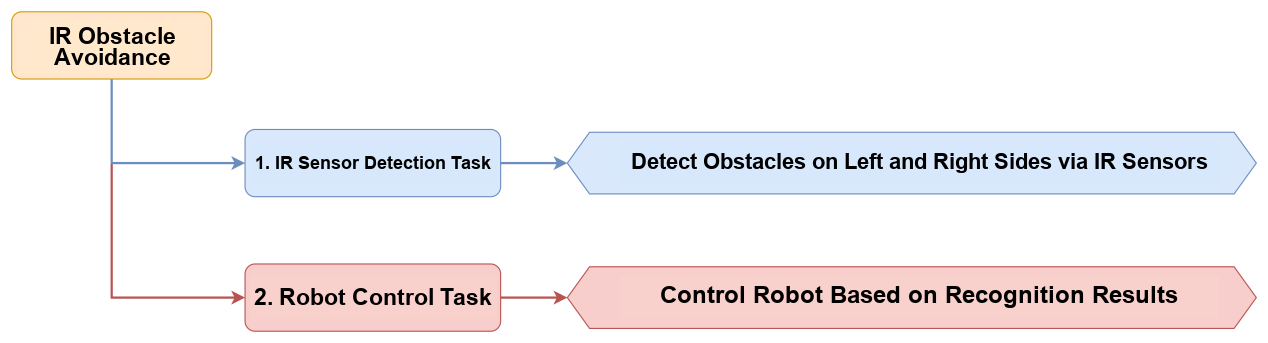
This section uses infrared obstacle avoidance sensors to detect obstacles and control robot movement.
6.3.10.2 Project Process
6.3.10.3 Module Description

The infrared obstacle avoidance sensor is used to detect whether there is an obstacle ahead. The sensor includes one infrared transmitter and one infrared receiver. Once the sensor encounters an obstacle, the infrared light is reflected back and received by the receiver.
Module wiring: before running this program, connect the module to the IO interfaces on the miniHexa base board at IO32, IO14, IO18, and IO19, as shown below.

Installation method: install the infrared obstacle avoidance sensors on the miniHexa back plate.

6.3.10.4 Program Download
Connect miniHexa to the PC with a Type-C data cable.
Open the Hiwonder Python Editor.
Open 10 Infrared Obstacle Avoidance Program/main.py, then drag it into the Hiwonder Python Editor. The drag operation takes effect only when the file is dropped inside the red box.
Click the connection icon in the menu bar
. After the connection succeeds, the icon turns green .After the connection succeeds, click the download icon
in the menu bar to download the program to miniHexa. Wait until the information panel below shows that the download is complete.
6.3.10.5 Project Outcome
After power-on, miniHexa uses two infrared obstacle avoidance sensors to detect obstacles around the body. If no obstacle is detected, miniHexa moves forward. If one side detects an obstacle, miniHexa turns away from the obstacle. If both sides detect obstacles, miniHexa first moves backward and then rotates in place.
6.3.10.6 Program Analysis
Import the libraries. The
Hiwonderlibrary is the robot control library.Hiwonder_DEVprovides the external sensor interface. Thetimelibrary is used for time-related operations.
import Hiwonder
import Hiwonder_DEV
import time
Create the robot object and initialize the pins of the two infrared obstacle avoidance sensors.
robot = Hiwonder.Robot()
ir1 = Hiwonder_DEV.DEV_IR(32)
ir2 = Hiwonder_DEV.DEV_IR(18)
Read the states of the two sensors.
    ir1_state = ir1.read()
    ir2_state = ir2.read()
When both sensors detect obstacles, miniHexa first moves backward for
2seconds and then rotates clockwise for2seconds.
    if ir1_state and ir2_state:  # Both sensors detect obstacles
        # Move backward for 2 seconds
        robot.go([0, -2, 0], 2, 800)
        time.sleep(2)

        # Rotate clockwise
        robot.go([0, 0, 2], 2, 800)
        time.sleep(2)
When only sensor
1detects an obstacle, miniHexa rotates clockwise for2seconds.
    elif ir1_state and not ir2_state:  # Only sensor 1 detects an obstacle
        # Rotate clockwise
        robot.go([0, 0, 2], 2, 800)
        time.sleep(2)
When only sensor
2detects an obstacle, miniHexa rotates counterclockwise for2seconds.
    elif not ir1_state and ir2_state:  # Only sensor 2 detects an obstacle
        # Rotate counterclockwise
        robot.go([0, 0, -2], 2, 800)
        time.sleep(2)
When neither sensor detects an obstacle, miniHexa keeps moving forward.
    else:  # Neither sensor detects an obstacle
        # Move forward continuously
        robot.go([0, 2, 0], -1, 800)
6.3.11 Intelligent Fall Prevention
6.3.11.1 Feature Overview
This section uses infrared obstacle avoidance sensors to detect an edge condition and controls robot movement to prevent a fall.
6.3.11.2 Project Process
6.3.11.3 Module Description
The infrared obstacle avoidance sensor is used to detect whether there is an obstacle ahead. The sensor includes one infrared transmitter and one infrared receiver. Once the sensor encounters an obstacle, the infrared light is reflected back and received by the receiver.
Module wiring: before running this program, connect the module to the IO interfaces on the miniHexa base board at IO32, IO14, IO18, and IO19, as shown below.

Installation method: install the infrared obstacle avoidance sensors on the front two legs of miniHexa.

6.3.11.4 Program Download
Connect miniHexa to the PC with a Type-C data cable.
Open the Hiwonder Python Editor.
Open 11 Intelligent Fall Prevention Program/main.py, then drag it into the Hiwonder Python Editor. The drag operation takes effect only when the file is dropped inside the red box.
Click the connection icon in the menu bar
. After the connection succeeds, the icon turns green .After the connection succeeds, click the download icon
in the menu bar to download the program to miniHexa. Wait until the information panel below shows that the download is complete.
6.3.11.5 Project Outcome
miniHexa uses the infrared obstacle avoidance sensors to detect edges near its legs to prevent falls. When either sensor is triggered, miniHexa moves backward and then rotates to change direction. Otherwise, miniHexa moves forward continuously.
6.3.11.6 Program Analysis
Import the libraries. The
Hiwonderlibrary is the robot control library.Hiwonder_DEVprovides the external sensor interface. Thetimelibrary is used for time-related operations.
import Hiwonder
import Hiwonder_DEV
import time
Create the robot object and initialize the pins of the two infrared obstacle avoidance sensors.
robot = Hiwonder.Robot()
ir1 = Hiwonder_DEV.DEV_IR(32)
ir2 = Hiwonder_DEV.DEV_IR(18)
Read the states of the two sensors.
    ir1_state = ir1.read()
    ir2_state = ir2.read()
If either sensor is triggered, miniHexa moves backward and then rotates to change its movement direction.
    # If either sensor is triggered
    if ir1_state or ir2_state:
        # Move backward quickly
        robot.go([0, -3, 0], 3, 1000)
        time.sleep(3)

        # Rotate
        robot.go([0, 0, 2], 4, 1000)
        time.sleep(4)
If neither sensor is triggered, miniHexa moves forward.
    else:
        # Move forward continuously
        robot.go([0, 3, 0])
6.4 AI Vision Project
6.4.1 ESP32-S3 AI Vision Module Overview and Installation
6.4.1.1 Product Introduction
The ESP32-S3 AI vision module is a compact camera module that can operate as a standalone system.
The built-in camera captures images. The ESP32 microcontroller processes the image data and transmits it through the Wi-Fi module. The module also supports multiple communication protocols and low-power operation, so it is widely used in IoT applications.
6.4.1.2 Interface Description

| Interface Name | Description |
|---|---|
| USB serial port | Serial communication and firmware flashing |
| Custom button | The button event can be customized in code |
| I2C Port | Interface for connecting to the controller for secondary development |
6.4.1.3 Notes
If water ripples appear in the images captured by the vision module, this may be caused by the rated input current of the module being ≤ 2A. Check the current output of the power supply.
The default image transmission program is preloaded at the factory. Flash the corresponding program when a vision recognition function is required.
6.4.1.4 Module Wiring
Use a 4-pin cable to connect the module to any I2C Port highlighted in red on the servo controller.

6.4.2 Getting Started
6.4.2.1 Notes
If the captured image shows water ripple patterns, the input power supply may provide a rated current of
2Aor less. Check the current output of the power supply.The image transmission firmware is preloaded at the factory. It can be tested directly without reflashing. Flash another firmware when another function is required.
6.4.2.2 Device Connection
Connect the AI vision module to the PC with a Type-C cable. Check in Device Manager that the port is recognized correctly.

Note
If the device does not appear under Ports, the driver may not be installed on the PC. The installation package is available at 2. Software/7.CH34x Driver Tool/ch341ser.exe. Install the driver manually if needed.
Connect to the hotspot generated by the module:
HW_ESP32S3CAM.


6.4.2.3 Image Transmission
Enter 192.168.5.1 in the browser address bar and press Enter. A phone browser or a PC browser can be used. A PC browser is used in the example below. In the page that opens, click  to enter the camera image transmission interface.

6.4.3 Controller-Device Communication Principle and Coordinate System Description
6.4.3.1 Introduction
This section introduces how the ESP32S3 module, abbreviated below as ESP32S3, communicates with controllers such as Arduino and ESP32 boards. It explains how the ESP32S3 operates as a device and how the controller accesses ESP32S3 data and control functions.
In this chapter, the ESP32S3 always operates as a device. Information is transmitted through the I2C protocol.
6.4.3.2 Controller-Device Relationship
In a controller-device system, the ESP32S3 operates as the device. Other microcontrollers and similar devices operate as the controller.
Functions of the ESP32S3 as the device
Receive and parse the signals sent by the controller:
Wait for an I2C signal interrupt. If I2C data is received, call the corresponding function according to the register address contained in the received I2C data.
Process data and send feedback:
When the ESP32S3 receives a register read command, call the corresponding transmission function and send the recognized data to the controller.
When the ESP32S3 receives a register setting command, set the fill light brightness.
Functions of other devices as the controller
Send commands:
Send a data read request to the ESP32S3.
Coordinate control:
Manage the coordinated operation of the entire system. Ensure that communication and operation among the controller, the ESP32S3, and other devices connected to the controller remain conflict-free and stable.
Receive data:
When the controller reads data, receive the status information sent by the ESP32S3 after the read command is sent. Then parse the data packet and extract the useful information.
6.4.3.3 Device Address and Registers
When the ESP32S3 runs the face detection function:
| Address | Function |
|---|---|
0x52 device address |
Communication address of the ESP32S3 |
0x01 register address |
Read face data [int16_t x, y, w, h]. All data values are 0 when no face is detected |
Note
In the face data, x, y, w, and h represent the face detection box marked in the original image. These values are the center point x coordinate, center point y coordinate, detection box width, and detection box height. The unit is pixels. See 6.4.3.4 Module Coordinate System Description for details about the pixel coordinate system used in this mode.
When the ESP32S3 runs the color recognition function:
| Address | Function |
|---|---|
0x52 device address |
Communication address of the ESP32S3 |
0x00 register address |
Read color 0 data. The returned data format is [int16_t x, y, w, h]. All data values are 0 when no target is detected |
0x01 register address |
Read color 1 data. The returned data format is [int16_t x, y, w, h]. All data values are 0 when no target is detected |
Note
In the color data,
x,y,w, andhrepresent the color block detection box marked in the original image. These values are the center pointxcoordinate, center pointycoordinate, detection box width, and detection box height. The unit is pixels. See 6.4.3.4 Module Coordinate System Description for details about the pixel coordinate system used in this mode.If multiple color blocks in the camera view match the preset color threshold, the module selects the two largest color blocks in the image and stores their detection box data in the
0x00and0x01register spaces in sequence.
6.4.3.4 Module Coordinate System Description
This section briefly introduces the image coordinate systems used when the module runs different functions. Review this section before studying the example programs.
When the example programs are ported for secondary development, establish the mapping between the module image coordinate system and the real-world coordinate system according to this document.
Pay attention to the following two characteristics of the module image coordinate system:
1. The origin is at the upper-left corner of the screen, not at the center of the screen.
2. The Y-axis direction is opposite to the Y-axis direction in a standard Cartesian coordinate system.
Image Transmission Mode

Note
The image transmission mode uses a resolution of 320 x 240 to match the image data interface used by the mobile app.
Face Detection Mode

Note
To ensure smooth image performance, the face detection mode uses a tested resolution of 240 x 240.
Color Recognition Mode

Note
To ensure smooth image performance, the color recognition mode uses a tested resolution of 160 x 140.
6.4.3.5 Notes
The controller and the ESP32S3 can use different power supplies. The grounds must be connected together during wiring. Stable communication voltage levels depend on a common ground.
6.4.4 Color Recognition
6.4.4.1 Feature Overview
This section uses the ESP32-S3 AI vision module to detect red, green, and blue color blocks. The RGB LEDs on the glowy ultrasonic module then light up in the corresponding color.
6.4.4.2 Project Process

6.4.4.3 Module Description
ESP32-S3 AI vision module

This development board integrates an ESP32-S3 chip and a camera module. After it is installed on the carrier board, it communicates through an I2C Port and can read color and face-detection data through I2C communication.
Module wiring: as shown below, connect the module to any I2C Port highlighted in red on the servo controller before running this program.

Glowy ultrasonic module

The module uses an I2C Port and can read the distance measured by the ultrasonic sensor through I2C communication. Two RGB LEDs are integrated at the ultrasonic probe position. The brightness can be adjusted. Color changes and color mixing across the red channel R, green channel G, and blue channel B make full-color lighting effects possible.
Note
The glowy ultrasonic module is already connected to the onboard I2C Port at the factory. No additional wiring is required.
6.4.4.4 Program Download
Program download for the ESP32-S3 AI vision module
(1) Connect the ESP32-S3 AI vision module to a USB port on the PC with a Type-C cable.
(2) Open 03 Program Files/01 Color Recognition/ColorDetection/ColorDetection.ino.

(3) Select ESP32S3 Dev Module as the development board.

(4) Click Tools in the menu bar. Configure the ESP32S3 development board options as shown below.

Note
Modify the development board configuration before downloading the program to the AI vision module.
(5) Finally, click  to download the code to the ESP32-S3 AI vision module. Wait until flashing is complete.


Program download for Python
(1) Connect miniHexa to the PC with a Type-C data cable.
(2) Open the Hiwonder Python Editor.
(3) Open 03 Program Files/01 Color Recognition/main.py. Then drag it into the Hiwonder Python Editor. The drag operation takes effect only when the file is dropped inside the red box.
(4) Click the connection icon in the menu bar . After the connection succeeds, the icon turns green .
(5) After the connection succeeds, click the download icon in the menu bar to download the program to miniHexa. Wait until the information panel below shows that the download is complete.
6.4.4.5 Project Outcome
When the AI vision module detects a red, green, or blue color block, the RGB LEDs on the glowy ultrasonic module light in the same color.
6.4.4.6 Program Analysis
Import the libraries.
Hiwonderis the robot control library.Hiwonder_DEVprovides the interface for external sensors.timeis used for time-related operations.
import Hiwonder
import Hiwonder_DEV
import time
Create the robot object, the ultrasonic sensor object, and the ESP32-S3 AI vision module object.
robot = Hiwonder.Robot()
sonar = Hiwonder_DEV.DEV_SONAR()
cam = Hiwonder_DEV.DEV_ESP32S3Cam()
If red is detected, set the RGB LEDs on the ultrasonic module to red.
  rec = cam.read_color(1)
  if rec:
    print("red")
    sonar.setRGB(0,250,0,0)
If green is detected, set the RGB LEDs on the ultrasonic module to green.
  else:
    rec = cam.read_color(2)
    if rec:
      print("green")
      sonar.setRGB(0,0,250,0)
If blue is detected, set the RGB LEDs on the ultrasonic module to blue.
    else:
      rec = cam.read_color(3)
      if rec:
        print("blue")
        sonar.setRGB(0,250,0,0)
6.4.5 Color Tracking
6.4.5.1 Feature Overview
This section uses the ESP32-S3 AI vision module to detect a red block. The robot then rotates in place to follow the movement of the block.
6.4.5.2 Project Process
6.4.5.3 Module Description
ESP32-S3 AI vision module
This development board integrates an ESP32-S3 chip and a camera module. After it is installed on the carrier board, it communicates through an I2C Port and can read color and face-detection data through I2C communication.
Module wiring: as shown below, connect the module to any I2C Port highlighted in red on the servo controller before running this program.
Glowy ultrasonic module
The module uses an I2C Port and can read the distance measured by the ultrasonic sensor through I2C communication. Two RGB LEDs are integrated at the ultrasonic probe position. The brightness can be adjusted. Color changes and color mixing across the red channel R, green channel G, and blue channel B make full-color lighting effects possible.
Note
The glowy ultrasonic module is already connected to the onboard I2C Port at the factory. No additional wiring is required.
6.4.5.4 Program Download
Program download for the ESP32-S3 AI vision module
(1) Connect the ESP32-S3 AI vision module to a USB port on the PC with a Type-C cable.
(2) Open 03 Program Files/02 Color Tracking/ColorTracking/ColorTracking.ino.
(3) Select ESP32S3 Dev Module as the development board.
(4) Click Tools in the menu bar. Configure the ESP32S3 development board options as shown below.
Note
Modify the development board configuration before downloading the program to the AI vision module.
(5) Finally, click to download the code to the ESP32-S3 AI vision module. Wait until flashing is complete.
Program download for Python
(1) Connect miniHexa to the PC with a Type-C data cable.
(2) Open the Hiwonder Python Editor.
(3) Open 03 Program Files/02 Color Tracking/main.py. Then drag it into the Hiwonder Python Editor. The drag operation takes effect only when the file is dropped inside the red box.
(4) Click the connection icon in the menu bar . After the connection succeeds, the icon turns green .
(5) After the connection succeeds, click the download icon in the menu bar to download the program to miniHexa. Wait until the information panel below shows that the download is complete.
6.4.5.5 Project Outcome
When the AI vision module detects a red block, the robot stays in place and adjusts its posture so that the AI vision module continues to face the red block.
Note
A rotation limit is set in the program. The robot tracks the color block only within 20° clockwise or counterclockwise from its current heading.
6.4.5.6 Program Analysis
Import the libraries.
Hiwonderis the robot control library.Hiwonder_DEVprovides the interface for external sensors.timeis used for time-related operations.
import Hiwonder
import Hiwonder_DEV
import time
Create the robot object, the ultrasonic sensor object, and the ESP32-S3 AI vision module object.
robot = Hiwonder.Robot()
sonar = Hiwonder_DEV.DEV_SONAR()
cam = Hiwonder_DEV.DEV_ESP32S3Cam()
fmapis a linear mapping function. It maps a value linearly from one range to another.
def fmap(x, in_min, in_max, out_min, out_max):
    return (x - in_min) * (out_max - out_min) / (in_max - in_min) + out_min
In the main loop, continuously read the color recognition result
recfrom the camera. If a target is detected andrecis valid, get the center pointxcoordinate fromrec[0]. Then map the center pointxcoordinate from[0, 160]to[-1, 1]and add the mapped value toyaw. Limityawto the range[-20, 20]. Finally, set the robot body angle and change only the yaw angle. Then wait0.05seconds.
while True:
  rec = cam.read_color(1)
  if rec:
    center = int(rec[0])
    yaw += fmap(center , 0 , 160 , -1 , 1)
    yaw = 20 if yaw > 20 else (-20 if yaw < -20 else yaw)
    robot.set_body_angle([0,0,yaw],100)
  time.sleep(0.05)
6.4.6 Visual Line Following
6.4.6.1 Feature Overview
This section uses the ESP32-S3 AI vision module to detect a red line and control the robot to follow the line.
6.4.6.2 Project Process

6.4.6.3 Module Description
ESP32-S3 AI vision module
This development board integrates an ESP32-S3 chip and a camera module. After it is installed on the carrier board, it communicates through an I2C Port and can read color and face-detection data through I2C communication.
Module wiring: as shown below, connect the module to any I2C Port highlighted in red on the servo controller before running this program.
Glowy ultrasonic module
The module uses an I2C Port and can read the distance measured by the ultrasonic sensor through I2C communication. Two RGB LEDs are integrated at the ultrasonic probe position. The brightness can be adjusted. Color changes and color mixing across the red channel R, green channel G, and blue channel B make full-color lighting effects possible.
Note
The glowy ultrasonic module is already connected to the onboard I2C Port at the factory. No additional wiring is required.
6.4.6.4 Program Download
Program download for the ESP32-S3 AI vision module
(1) Connect the ESP32-S3 AI vision module to a USB port on the PC with a Type-C cable.
(2) Open 03 Program Files/03 Vision Line Following/LineFollowing/LineFollowing.ino.
(3) Select ESP32S3 Dev Module as the development board.
(4) Click Tools in the menu bar. Configure the ESP32S3 development board options as shown below.
Note
Modify the development board configuration before downloading the program to the AI vision module.
(5) Finally, click to download the code to the ESP32-S3 AI vision module. Wait until flashing is complete.
Program download for Python
(1) Connect miniHexa to the PC with a Type-C data cable.
(2) Open the Hiwonder Python Editor.
(3) Open 03 Program Files/03 Vision Line Following/main.py. Then drag it into the Hiwonder Python Editor. The drag operation takes effect only when the file is dropped inside the red box.
(4) Click the connection icon in the menu bar . After the connection succeeds, the icon turns green .
(5) After the connection succeeds, click the download icon in the menu bar to download the program to miniHexa. Wait until the information panel below shows that the download is complete.
6.4.6.5 Project Outcome
When the AI vision module detects a red line, the robot moves along the line.
6.4.6.6 Program Analysis
Import the libraries.
Hiwonderis the robot control library.Hiwonder_DEVprovides the interface for external sensors.timeis used for time-related operations.
import Hiwonder
import Hiwonder_DEV
import time
Create the robot object and the ESP32-S3 AI vision module object.
robot = Hiwonder.Robot()
cam = Hiwonder_DEV.DEV_ESP32S3Cam()
If the
xcoordinate of the center point of the color region is greater than120, move the robot toward the front right.
  if rec:
    if rec[0] > 120:
      robot.go([0,1,-0.1])
If the
xcoordinate of the center point of the color region is less than40, move the robot toward the front left.
    elif rec[0] < 40:
      robot.go([0,1,0.1])
Otherwise, move the robot straight forward.
    else:
      robot.go([0,1,0])
6.4.7 Face Detection
6.4.7.1 Feature Overview
This section uses the ESP32-S3 AI vision module to detect faces. Once a face is detected, miniHexa performs a cute action.
6.4.7.2 Project Process

6.4.7.3 Module Description
ESP32-S3 AI vision module
This development board integrates an ESP32-S3 chip and a camera module. After it is installed on the carrier board, it communicates through an I2C Port and can read color and face-detection data through I2C communication.
Module wiring: as shown below, connect the module to any I2C Port highlighted in red on the servo controller before running this program.
Glowy ultrasonic module
The module uses an I2C Port and can read the distance measured by the ultrasonic sensor through I2C communication. Two RGB LEDs are integrated at the ultrasonic probe position. The brightness can be adjusted. Color changes and color mixing across the red channel R, green channel G, and blue channel B make full-color lighting effects possible.
Note
The glowy ultrasonic module is already connected to the onboard I2C Port at the factory. No additional wiring is required.
6.4.7.4 Program Download
Program download for the ESP32-S3 AI vision module
(1) Connect the ESP32-S3 AI vision module to a USB port on the PC with a Type-C cable.
(2) Open 03 Program Files/04 Face Recognition/FaceDetection/FaceDetection.ino.

(3) Select ESP32S3 Dev Module as the development board.
(4) Click Tools in the menu bar. Configure the ESP32S3 development board options as shown below.
Note
Modify the development board configuration before downloading the program to the AI vision module.
(5) Finally, click to download the code to the ESP32-S3 AI vision module. Wait until flashing is complete.
Program download for Python
(1) Connect miniHexa to the PC with a Type-C data cable.
(2) Open the Hiwonder Python Editor.
(3) Open 03 Program Files/04 Face Recognition/main.py. Then drag it into the Hiwonder Python Editor. The drag operation takes effect only when the file is dropped inside the red box.
(4) Click the connection icon in the menu bar . After the connection succeeds, the icon turns green .
(5) After the connection succeeds, click the download icon in the menu bar to download the program to miniHexa. Wait until the information panel below shows that the download is complete.
6.4.7.5 Project Outcome
When a face is detected, the robot pitches forward and backward twice within ±10° and then returns to a level posture.
6.4.7.6 Program Analysis
Import the libraries.
Hiwonderis the robot control library.Hiwonder_DEVprovides the interface for external sensors.timeis used for time-related operations.
import Hiwonder
import Hiwonder_DEV
import time
Create the robot object and the ESP32-S3 AI vision module object.
robot = Hiwonder.Robot()
cam = Hiwonder_DEV.DEV_ESP32S3Cam()
Use
read_face()to get the face data. If a face is detected, the function returns the face position array[x, y, w, h]. If no face is detected, the function returnsNone. Store the returned data inrec.
while True:
  rec = cam.read_face()
If face data is returned, control miniHexa to pitch forward and backward within ±10° and then return to a level posture.
  if rec:
    if rec[2] > 0:
      # Pitch +10 degrees
      robot.set_body_angle([0, 10, 0], 300)
      time.sleep_ms(300)
      # Pitch -10 degrees
      robot.set_body_angle([0, -10, 0], 300)
      time.sleep_ms(300)
      # Pitch +10 degrees
      robot.set_body_angle([0, 10, 0], 300)
      time.sleep_ms(300)
      # Pitch -10 degrees
      robot.set_body_angle([0, -10, 0], 300)
      time.sleep_ms(300)
      # Return to the level posture
      robot.set_body_angle([0, 0, 0], 300)
      time.sleep_ms(300)
set_body_angle() is the function that sets the body angle of miniHexa. Use set_body_angle([0, 10, 0], 300) as the example.
The first parameter [0, 10, 0] represents the body angles [roll, pitch, yaw]. The range is ±20°.
The second parameter 300 is the running time.
Call
set_body_pose()to move miniHexa2 cmto the right first and then2 cmto the left. After this sequence is executed twice, return to the center position.
      # Move 2 cm to the right
      robot.set_body_pose([2.0, 0, 0], 200)
      time.sleep_ms(200)
      # Move 2 cm to the left
      robot.set_body_pose([-2.0, 0, 0], 200)
      time.sleep_ms(200)
      # Move 2 cm to the right
      robot.set_body_pose([2.0, 0, 0], 200)
      time.sleep_ms(200)
      # Move 2 cm to the left
      robot.set_body_pose([-2.0, 0, 0], 200)
      time.sleep_ms(200)
      # Return to the center position
      robot.set_body_pose([0, 0, 0], 200)
      time.sleep_ms(200)
set_body_pose() is the function that sets the x, y, and z offsets of the miniHexa body from the origin. Use set_body_pose([2.0, 0, 0], 200) as the example.
The first parameter [2.0, 0, 0] is the x, y, and z offset of the body center from the origin. The range is [-4.0f, 4.0f]. The unit is centimeters.
The second parameter 200 is the time used for each step.
6.5 AI Voice Project
6.5.1 Introduction and Installation of WonderEcho
6.5.1.1 Module Introduction

The integrated voice interaction module WonderEcho is built on the CI1302 chip for voice recognition and voice playback. It supports offline neural network acceleration and hardware acceleration for voice signal processing. The module uses deep noise reduction and neural network models to analyze voice input and generate recognition results.
The CI1302 chip integrates a Brain Neural Processing Unit, supports offline neural network acceleration and hardware acceleration for voice signal processing, and runs at up to 220MHz. It supports offline far-field voice recognition, includes 2MB of onboard FLASH storage, and can store up to 300 command words.
The module is easy to use and delivers strong voice recognition performance. It is widely used in smart home devices, conversational robots, educational robots, and in-vehicle dispatch terminals.
Working Principle
The module uses a wake-word activation mode. Speak the wake word first to activate the voice interaction module. Commands can be recognized only after activation.
English is the default recognition language. The default English wake word is Hello Hiwonder.
If no voice is recognized within 15 seconds, the module enters sleep mode. Wake the module again before the next use.
After the CI1302 chip recognizes a command word, it sends the corresponding instruction to the I2C chip and plays back the matching phrase. The I2C chip stores the received voice command and send it through the I2C device protocol. The supported command words are listed in 03 WonderEcho Firmware Flash Tutorial/Command Word and Playback Phrase Protocol List.
Notes
Use a
5Vpower supply. Incorrect voltage may damage the module.Use the module in a quiet environment. Excessive background noise affects recognition performance.
Speak the command words clearly and loudly. Avoid speaking too quickly. A distance of less than
5meters from the module is recommended.
6.5.1.2 Hardware Interface Description


| No. | Hardware Name | Description |
|---|---|---|
| 1 | Speaker | Converts analog signals into sound |
| 2 | Microphone | Converts sound into analog signals |
| 3 | RST button | Reset button |
| 4 | Signal indicator blue LED | Stays on during operation. Flashes once when a command word is recognized |
| 5 | Power indicator red LED | Stays on when the power supply is normal |
| 6 | I2C Port | Works as an I2C device and is used for power supply and communication with the controller |
| 7 | Type-C Port | Used for power supply and CI1302 firmware updates |
| 8 | CI1302 chip | High-performance voice recognition chip that recognizes voice commands and outputs signals |
| 9 | I2C chip | Converts instructions from the voice recognition chip into I2C protocol commands |
| 10 | Audio amplifier chip | Converts digital signals into analog signals to drive the speaker |
6.5.2 Introduction to the Voice Module Library Files
WonderEcho Code Blocks
Module initialization
Use the following code to initialize the module interface.
asr = Hiwonder_DEV.DEV_ASR()
Retrieve the command word ID
This code block retrieves the ID of the command word recognized by the module. The return value is an integer.
result = asr.getResult()
Play back a specified entry by ID
This function requires two parameters. cmd is the type ID of the entry to be played back. 0xFF is the playback type and 0x00 is the command type. id is the ID of the entry to be played back. The module receives the data through the I2C protocol and actively plays back the specified entry.
asr.speak()
6.5.3 Voice Obstacle Alert
6.5.3.1 Feature Overview
This section uses the ultrasonic module to detect obstacles in front of the robot. When an obstacle is too close, the ultrasonic module and the voice interaction module provide a sound and light alert.
6.5.3.2 Project Process

6.5.3.3 Module Description
WonderEcho voice interaction module

The integrated voice interaction module WonderEcho is built on the CI1302 chip for voice recognition and voice playback. It supports offline neural network acceleration and hardware acceleration for voice signal processing. The module uses deep noise reduction and neural network models to analyze voice input and generate recognition results.
Module wiring: as shown below, connect the module to any I2C Port highlighted in red on the servo controller before running this program.

Installation: mount the voice interaction module on the rear panel of miniHexa.

Glowy ultrasonic module

The module uses an I2C communication interface and can read the distance measured by the ultrasonic sensor through I2C communication. Two RGB LEDs are integrated at the ultrasonic probe position. The brightness can be adjusted. Color changes and color mixing across the red channel R, green channel G, and blue channel B make full-color lighting effects possible.
Note
The glowy ultrasonic module is already connected to the onboard I2C Port at the factory. No additional wiring is required.
6.5.3.4 Program Download
Connect miniHexa to the PC with a Type-C data cable.
Open the Hiwonder Python Editor.
Open 02 Program Files/01 Voice Obstacle Alert Program/main.py. Then drag it into the Hiwonder Python Editor. The drag operation takes effect only when the file is dropped inside the red box.
Click the connection icon in the menu bar
. After the connection succeeds, the icon turns green .After the connection succeeds, click the download icon in the menu bar
to download the program to miniHexa. Wait until the information panel below shows that the download is complete.
6.5.3.5 Project Outcome
When the glowy ultrasonic module detects no obstacle ahead or the obstacle is too far away, the module lights up green. When the obstacle is too close, the module lights up red and the voice interaction module plays back Obstacle ahead.
6.5.3.6 Program Analysis
Import the libraries.
Hiwonderis the robot control library.Hiwonder_DEVprovides the interface for external sensors.timeis used for time-related operations.
import Hiwonder
import Hiwonder_DEV
import time
Create the robot object and initialize WonderEcho and the glowy ultrasonic module.
robot = Hiwonder.Robot()
sonar = Hiwonder_DEV.DEV_SONAR()
asr = Hiwonder_DEV.DEV_ASR()
Get the distance returned by the ultrasonic module.
while True:
    dis = sonar.getDistance()
If the distance is less than
15, set the RGB LEDs on the ultrasonic module to red. Then make the voice interaction module play backObstacle ahead.
    if dis < 15:
      r, g, b = 255, 0, 0
      sonar.setRGB(0, r, g, b)
      asr.speak(asr.ASR_ANNOUNCER, 5)
      time.sleep(1.5)
If the distance is greater than or equal to
15, set the RGB LEDs on the ultrasonic module to green.
    else:
      r, g, b = 0, 255, 0
      sonar.setRGB(0, r, g, b)
    time.sleep_ms(100)
6.5.4 Human-Robot Interaction
6.5.4.1 Feature Overview
This section uses the voice interaction module to detect commands and respond with different actions.
6.5.4.2 Project Process

6.5.4.3 Preparation
Module installation
The integrated voice interaction module WonderEcho is built on the CI1302 chip for voice recognition and voice playback. It supports offline neural network acceleration and hardware acceleration for voice signal processing. The module uses deep noise reduction and neural network models to analyze voice input and generate recognition results.
Module wiring: as shown below, connect the module to any I2C Port highlighted in red on the servo controller before running this program.
Installation: mount the voice interaction module on the rear panel of miniHexa.
6.5.4.4 Action Group Download
Follow the instructions in 6.3 Secondary Development Project -> 6.3.1.3 Action Group Download to download the action groups to miniHexa.
6.5.4.5 Program Download
Connect miniHexa to the PC with a Type-C data cable.
Open the Hiwonder Python Editor.
Open 02 Program Files/02 Human-Robot Interaction Program/main.py. Then drag it into the Hiwonder Python Editor. The drag operation takes effect only when the file is dropped inside the red box.
Click the connection icon in the menu bar
. After the connection succeeds, the icon turns green .After the connection succeeds, click the download icon in the menu bar
to download the program to miniHexa. Wait until the information panel below shows that the download is complete.
6.5.4.6 Project Outcome
When a specified command word is recognized, the robot executes the corresponding action group as a response. The mapping between the command word and the action group is as follows:
| Spoken Command | Voice Module Response | Executed Action |
|---|---|---|
Hello |
Hi |
Run Action Group 14 |
Introduce Yourself |
Hello, i'm Hiwonder, and i can talk and dance. |
Perform the cute action |
Show a Skill |
Watch closely |
Run Action Group 7 |
6.5.4.7 Program Analysis
Import the libraries.
Hiwonderis the robot control library.Hiwonder_DEVprovides the interface for external sensors.timeis used for time-related operations.
import Hiwonder
import Hiwonder_DEV
import time
Create the robot object and initialize WonderEcho and the glowy ultrasonic module.
robot = Hiwonder.Robot()
sonar = Hiwonder_DEV.DEV_SONAR()
asr = Hiwonder_DEV.DEV_ASR()
perform_dance()is the function that performs the cute action. It usesset_body_angle()andset_body_pose().
set_body_angle() is the function that sets the body angle. The first parameter is the body angle [roll, pitch, yaw]. The range is [-20.0, 20.0] degrees. The second parameter is the execution time and is optional.
set_body_pose() is the function that sets the x, y, and z offsets of the body from the origin. The first parameter is the x, y, and z offset of the body center from the origin. The range is [-4.0, 4.0]. The second parameter is the execution time for each step and is optional.
def perform_dance():
    global robot
    # Part 1: Pitch swing
    # Pitch +10 degrees, body leans forward
    robot.set_body_angle([0.0, 10.0, 0.0], 300)
    time.sleep_ms(600)  # Wait for the action to finish plus extra delay

    # Pitch -10 degrees, body leans backward
    robot.set_body_angle([0.0, -10.0, 0.0], 300)
    time.sleep_ms(600)

    # Pitch +10 degrees, body leans forward
    robot.set_body_angle([0.0, 10.0, 0.0], 300)
    time.sleep_ms(600)

    # Pitch -10 degrees, body leans backward
    robot.set_body_angle([0.0, -10.0, 0.0], 300)
    time.sleep_ms(600)

    # Return to the level posture
    robot.set_body_angle([0.0, 0.0, 0.0], 300)
    time.sleep_ms(600)

    # Part 2: Horizontal swing along the x-axis
    # Move 2 cm to the right
    robot.set_body_pose([2.0, 0.0, 0], 200)
    time.sleep_ms(400)

    # Move 2 cm to the left
    robot.set_body_pose([-2.0, 0.0, 0], 200)
    time.sleep_ms(400)

    # Move 2 cm to the right
    robot.set_body_pose([2.0, 0.0, 0], 200)
    time.sleep_ms(400)

    # Move 2 cm to the left
    robot.set_body_pose([-2.0, 0.0, 0], 200)
    time.sleep_ms(400)

    # Return to the center position
    robot.set_body_pose([0.0, 0.0, 0], 200)
    time.sleep_ms(400)
Get the ID corresponding to the recognized command word.
result = asr.getResult()
When the recognized command word is
Hello, run Action Group 14.
    if result == 26:
        # "Hello" recognized - run Action Group 14
        robot.action_group_run(14)
When the recognized command word is
Introduce Yourself, perform the cute action.
    elif result == 27:
        # "Introduce Yourself" recognized - perform the cute action
        perform_dance()
When the recognized command word is
Show a Skill, run Action Group 7.
    elif result == 28:
        # "Show a Skill" recognized - run Action Group 7
        robot.action_group_run(7)
6.5.5 Voice Control
6.5.5.1 Feature Overview
This section uses the voice interaction module to detect spoken commands and execute the corresponding movements.
6.5.5.2 Project Process

6.5.5.3 Module Description
The integrated voice interaction module WonderEcho is built on the CI1302 chip for voice recognition and voice playback. It supports offline neural network acceleration and hardware acceleration for voice signal processing. The module uses deep noise reduction and neural network models to analyze voice input and generate recognition results.
Module wiring: as shown below, connect the module to any I2C Port highlighted in red on the servo controller before running this program.
Installation: mount the voice interaction module on the rear panel of miniHexa.
6.5.5.4 Program Download
Connect miniHexa to the PC with a Type-C data cable.
Open the Hiwonder Python Editor.
Open 02 Program Files/03 Voice Control Program/main.py. Then drag it into the Hiwonder Python Editor. The drag operation takes effect only when the file is dropped inside the red box.
Click the connection icon in the menu bar
. After the connection succeeds, the icon turns green .After the connection succeeds, click the download icon in the menu bar
to download the program to miniHexa. Wait until the information panel below shows that the download is complete.
6.5.5.5 Project Outcome
When a specified command word is recognized, the robot executes the corresponding movement as a response. The mapping between the command word and the movement is as follows:
| Spoken Command | Voice Module Response | Executed Movement |
|---|---|---|
Go straight |
Going straight |
Move forward continuously |
Go backward |
Going backward |
Move backward continuously |
Turn left |
Turning left |
Rotate counterclockwise continuously |
Turn right |
Turning right |
Rotate clockwise continuously |
Stop |
Copy that |
Stop moving |
March |
Copy that |
Move forward two steps in the current heading |
6.5.5.6 Program Analysis
Import the libraries.
Hiwonderis the robot control library.Hiwonder_DEVprovides the interface for external sensors.timeis used for time-related operations.
import Hiwonder
import Hiwonder_DEV
import time
Create the robot object and initialize WonderEcho.
robot = Hiwonder.Robot()
asr = Hiwonder_DEV.DEV_ASR()
Define the command ID for each spoken command.
FORWARD_ID = 1      # "Go straight"
BACKWARD_ID = 2     # "Go backward"
LEFT_ID = 3         # "Turn left"
RIGHT_ID = 4        # "Turn right"
STOP_ID = 9         # "Stop"
WALK_ID = 29        # "March"
Get the ID corresponding to the recognized command word.
# Main loop
while True:
    # Run voice recognition
    result = asr.getResult()
If the recognized command word is
Go straight, miniHexa moves forward.
    if result == FORWARD_ID:
        # Go straight
        robot.go([0.0, 2.0, 0.0])
If the recognized command word is
Go backward, miniHexa moves backward.
    elif result == BACKWARD_ID:
        # Go backward
        robot.go([0.0, -2.0, 0.0])
If the recognized command word is
Turn left, miniHexa turns left.
    elif result == LEFT_ID:
        # Turn left
        robot.go([0.0, 0.0, 2.0])
If the recognized command word is
Turn right, miniHexa turns right.
    elif result == RIGHT_ID:
        # Turn right
        robot.go([0.0, 0.0, -2.0])
If the recognized command word is
Stop, miniHexa stops moving.
    elif result == STOP_ID:
        # Stop
        robot.go([0.0, 0.0, 0.0])
If the recognized command word is
March, miniHexa moves forward for two steps.
    elif result == WALK_ID:
        # "March" - move forward two steps
        robot.go([0.0, 2.0, 0.0],2)
        time.sleep(2)